
Transparent sealing member

a sealing member and transparent technology, applied in the field of transparent sealing members, can solve the problems of reducing the sterilizing effect due to ultraviolet light, the amount of ultraviolet light emitted from the optical element, and the decrease of the ultraviolet light emitted, so as to suppress the decrease in the sterilizing effect and easy peeling

Active Publication Date: 2020-05-14
NGK INSULATORS LTD
View PDF0 Cites 0 Cited by
  • Summary
  • Abstract
  • Description
  • Claims
  • Application Information

AI Technical Summary

Benefits of technology

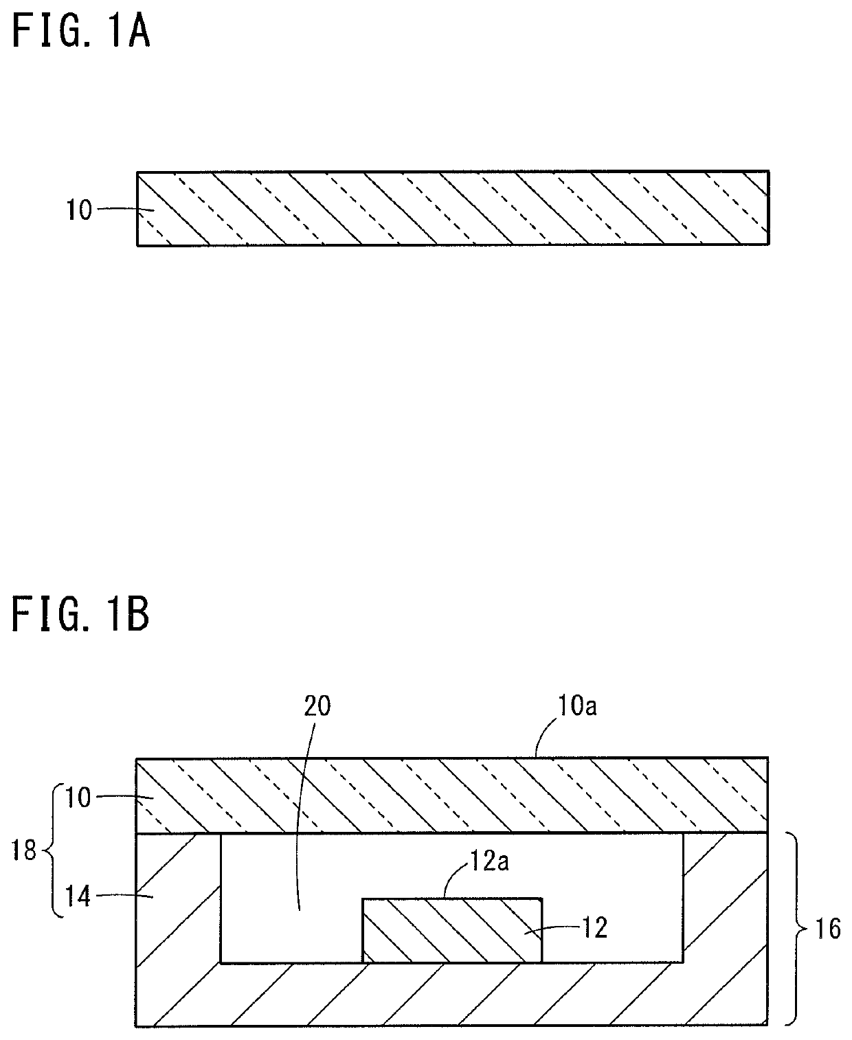
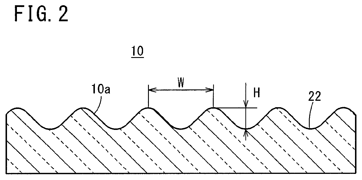
The present invention provides a transparent sealing member with minute recesses on its surface that help prevent contaminants from adhering and make them easier to peel off. This also helps maintain the sterilizing effect by reducing the contact area with foulants and suppressing a decrease in light transmission.

Problems solved by technology

In such cases, a problem of fouling is known in which, for example, the amount of ultraviolet light emitted from the optical element decreases at the surface of the transparent sealing member, and the sterilizing effect due to ultraviolet light decreases.
In such cases, the problem of fouling is known in which, for example, the amount of ultraviolet light emitted from the optical element decreases at the surface of the transparent sealing member, and the sterilizing effect due to ultraviolet light decreases.

Method used


Image

  • Transparent sealing member
  • Transparent sealing member
  • Transparent sealing member

Examples


exemplary embodiment 2 (

[Exemplary Embodiment 2 (Sample 2)]

[0045]The transparent sealing member according to Exemplary Embodiment 2 (Sample 2) was manufactured in the same manner as in Sample 1, except that the manufactured silica powder dried body was calcined at 500° C. in the atmosphere, and thereafter was fired in a hydrogen atmosphere at a temperature that was 10° C. lower than that of Sample 1.

exemplary embodiment 3 (

[Exemplary Embodiment 3 (Sample 3)]

[0046]The transparent sealing member according to Exemplary Embodiment 3 (Sample 3) was manufactured in the same manner as in Sample 1, except that the manufactured silica powder dried body was calcined at 500° C. in the atmosphere, and thereafter was fired in a hydrogen atmosphere at a temperature that was 20° C. lower than that of Sample 1.


PUM

PropertyMeasurementUnit
depthaaaaaaaaaa
depthaaaaaaaaaa
surface roughnessaaaaaaaaaa

Abstract

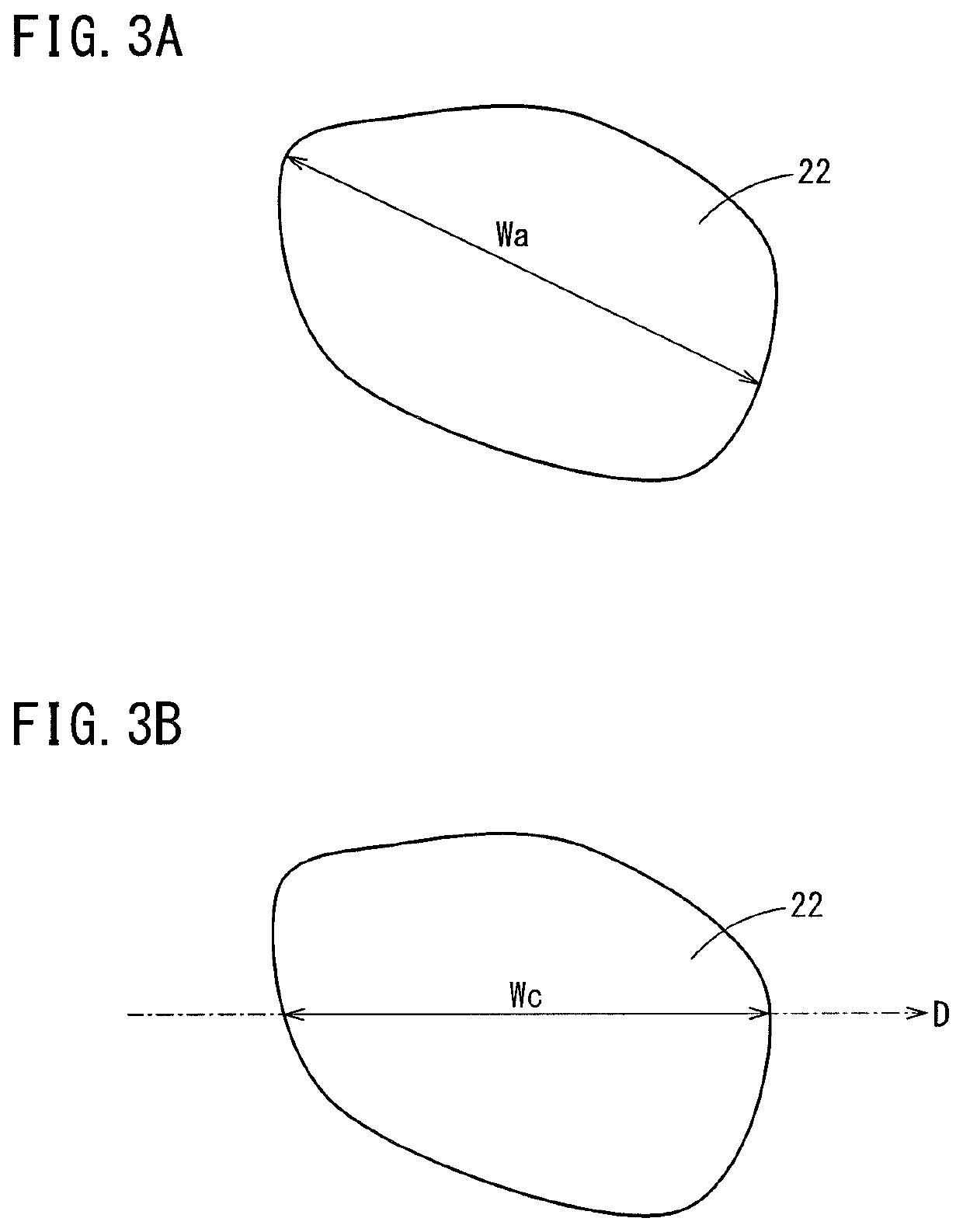
A transparent sealing member is provided with minute recesses at least in the surface of the member from which light from an optical element is emitted. The average width of the minute recesses is 0.1 μm to 2.0 μm, the average depth of the minute recesses is 5 nm to 50 nm, and the average frequency of occurrence of the minute recesses is 100000 to 3000000 recesses per 1 mm2.

Description

CROSS-REFERENCE TO RELATED APPLICATIONS[0001]This application is a Continuation of International Application No. PCT / JP2018 / 011898 filed on Mar. 23, 2018, which is based upon and claims the benefit of priority from International Application No. PCT / JP2017 / 025305 filed on Jul. 11, 2017, the contents all of which are incorporated herein by reference.TECHNICAL FIELD[0002]The present invention relates to a transparent sealing member which is used with an optical component, for example, such as an LED (light emitting diode), an LD (semiconductor laser), or the like.BACKGROUND ART[0003]Recently, methods of using a light emitting element (ultraviolet LED) that emits ultraviolet rays for the purposes of sterilization and purification are becoming widespread. In such an ultraviolet LED device, a transparent sealing member is required in order to protect the light emitting element from the outside air and moisture. From the standpoints of permeability to ultraviolet rays and durability, glass...

Claims


Application Information

Patent Timeline
Patent Type & Authority Applications(United States)
IPC IPC(8): F21K9/66F21K9/235C03C3/06
CPCF21K9/235C03C3/06F21K9/66H01L33/54H01L33/58H01L2933/0058H01L2933/0091H01L33/486H01L33/56
Inventor KIKUCHI, YOSHIOSHIBATA, HIROYUKIHISHIKI, TATSUYA
Owner NGK INSULATORS LTD
Learn More