Methods and systems for optimizing selection and placement of cochlear implant electrode arrays using patient-specific cochlear information and applications of same

a cochlear implant and electrode array technology, applied in the field of cochlear implants, can solve the problems of poorer outcomes, low patient-specific attention for optimizing placement of patient-specific electrode arrays, and no patient-specific approach is in widespread use today, and achieves the effect of improving outcomes

Active Publication Date: 2020-05-07
VANDERBILT UNIV
View PDF0 Cites 2 Cited by
  • Summary
  • Abstract
  • Description
  • Claims
  • Application Information

AI Technical Summary

Benefits of technology

[0009]One of the objectives of the invention is to develop and validate pre-operative CT image-analysis and intra-operative guidance techniques for optimizing selection and placement of CI electrode arrays on a patient-personalized basis, with the ultimate goal of improving outcomes.

Problems solved by technology

Despite the overwhelming evidence that sub-optimal array placement is linked with poorer outcomes, few technologies have been introduced in the past few decades that improve the surgical placement of the array with most focused on electrode array design and generic insertion guidelines applied to entire populations rather than individuals, despite the fact that no single array design could lead to optimal placement for most individuals due to the large inter-patient variations in the size and shape of the cochlea that have been well documented [13-14].
The use of patient-specific information to optimize placement has received relatively minimal attention, and no patient-specific approaches are in widespread use today.
One factor that has limited development in this area is that it has been difficult to measure patient-specific differences cochlear anatomy because the cochlea is difficult to image.
This technological barrier has prevented precise and accurate quantification of patient-specific cochlear anatomy.
In addition to lack of precision, procedures available have been labor intensive, posing a barrier for clinical adoption of patient-specific analyses.
Therefore, a heretofore unaddressed need exists in the art to address the aforementioned deficiencies and inadequacies.

Method used


Image

  • Methods and systems for optimizing selection and placement of cochlear implant electrode arrays using patient-specific cochlear information and applications of same
  • Methods and systems for optimizing selection and placement of cochlear implant electrode arrays using patient-specific cochlear information and applications of same
  • Methods and systems for optimizing selection and placement of cochlear implant electrode arrays using patient-specific cochlear information and applications of same

Examples


example

Preliminary Results with Image-Guided Cochlear Implant Insertion Techniques

[0240]In this exemplary example, we present preliminary results from a blinded, randomized temporal bone study comparing final EA position for cochleae implanted with customized optimal insertion plans versus suboptimal insertion plans.

Methods

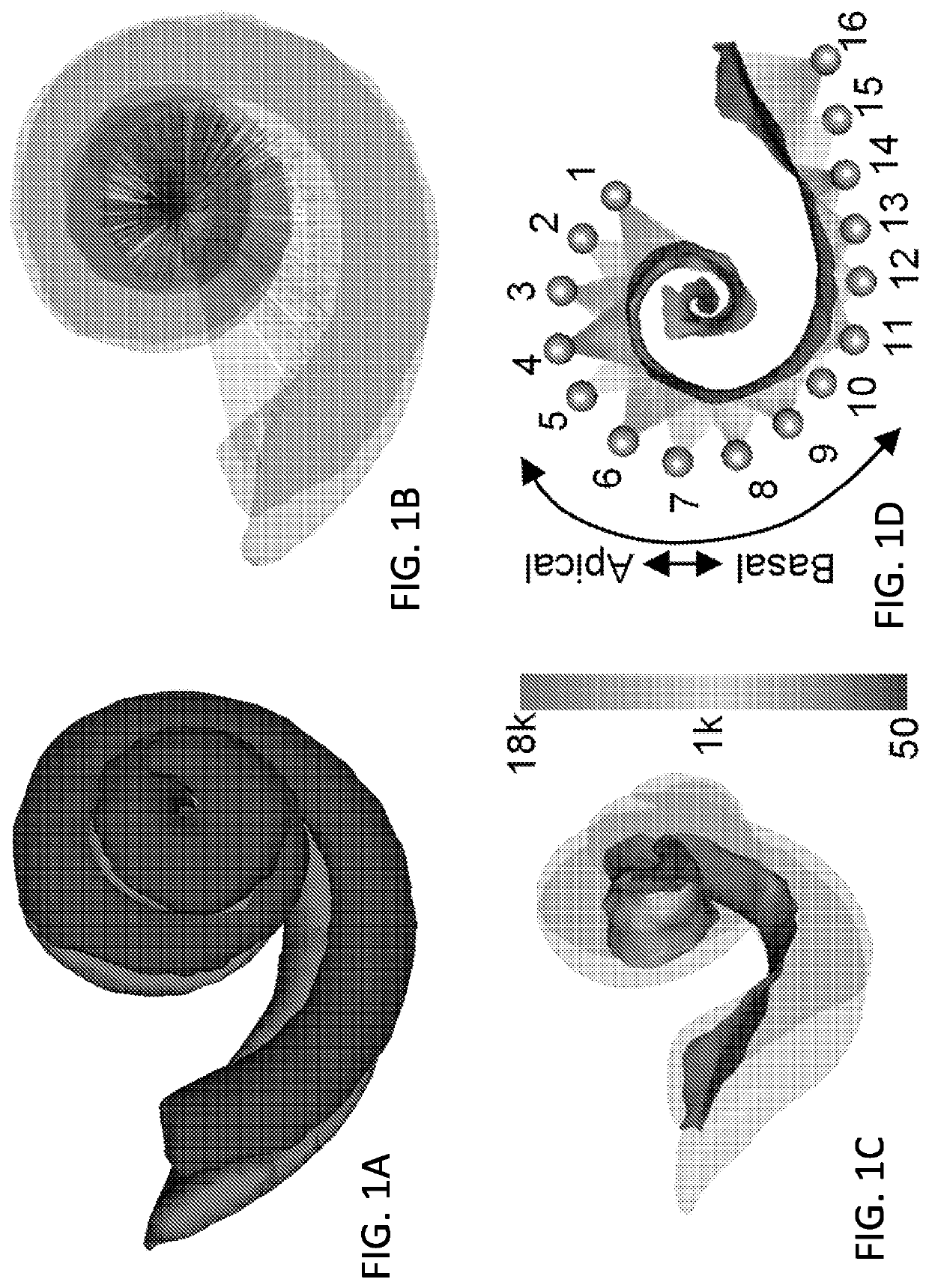
[0241]According to the invention, analysis of temporal bone anatomy, i.e., the shape of ST and SV, in the pre-operative CT image can be used to recommend an approach vector, array base insertion depth, and AOS depth and orientation for pre-curved EAs. To segment ST and SV, we use a shale model such as a non-rigid statistical shape model [27] created with μCT images of 9 cochleae specimens in which intra-cochlear structures are visible [11-12]. These models are then automatically fit to the external boundary of the patient cochlea that is visible in conventional CT allowing highly accurate estimation of the position of internal cochlear structures not visible in the CT. F...


PUM


Abstract

A method for using information of patient-specific cochlea size and/or shape to determine a patient-customized cochlear implant electrode insertion and placement plan includes segmenting shapes of structures of interest (SOIs) of the cochlea in a pre-operative CT image of the cochlea using a shape model; defining a 3D modiolar hugging curve within the shape model of the SOIs as a sequence of points; automatically transforming the defined 3D modiolar hugging curve to the pre-operative CT image so as to obtain a modiolar curve in the cochlea; rigidly registering an EA shape model of the EA to the modiolar curve in the cochlea, thereby placing a resting state shape of the EA within the patient's SOIs such that the EA matches the modiolar curve in the cochlea; and determining a patient-customized insertion plan for electrode placement using the registered EA shape model.

Description

CROSS-REFERENCE TO RELATED PATENT APPLICATIONS[0001]This PCT application claims priority to and the benefit of, pursuant to 35 U.S.C. § 119(e), U.S. Provisional Patent Application Ser. Nos. 62 / 489,005, filed Apr. 24, 2017, and 62 / 540,669 filed Aug. 3, 2017, which are incorporated herein in their entireties by reference.[0002]Some references, which may include patents, patent applications and various publications, are cited and discussed in the description of this disclosure. The citation and / or discussion of such references is provided merely to clarify the description of the present disclosure and is not an admission that any such reference is “prior art” to the disclosure described herein. All references cited and discussed in this specification are incorporated herein by reference in their entireties and to the same extent as if each reference was individually incorporated by reference. In terms of notation, hereinafter, “[n]” represents the nth reference cited in the reference l...

Claims


Application Information

Patent Timeline
Patent Type & Authority Applications(United States)
IPC IPC(8): A61N1/36A61B34/10A61N1/05A61B5/055A61B5/107
CPCA61N1/0541A61B34/10A61B2505/05A61N1/36039A61B5/055A61B5/1076A61B2562/043A61B6/03A61N1/36036A61N1/37518G16H20/40A61B6/12A61B6/5217A61B5/686A61B5/1072G16H50/50A61B2034/2055A61B2034/105A61B2034/107A61B2034/108G06T7/181G06T7/12A61B6/032G06T11/005G06T2207/30008G06T2211/424
Inventor NOBLE, JACK H.LABADIE, ROBERT F.DAWANT, BENOIT M.
Owner VANDERBILT UNIV
Why Eureka
Try Eureka