
Method for medical device localization based on magnetic and impedance sensors

Pending Publication Date: 2020-05-07
ST JUDE MEDICAL CARDILOGY DIV INC
View PDF0 Cites 16 Cited by
  • Summary
  • Abstract
  • Description
  • Claims
  • Application Information

AI Technical Summary

Benefits of technology

The patent describes a system that predicts the position of a medical device within a three-dimensional space using measurements of electrical resistance and magnetic field data. The system uses models that are constantly updated based on the measured data to improve its accuracy. The system can estimate the position of the device by integrating the predicted and measured data with external parameters like position and orientation. The estimated position can then be used to guide the device to its target location during a medical procedure. The technology uses an extended Kalman filter to refine the transformations and improve the correspondence of the models with the physical system.

Problems solved by technology

However, because electrical impedance-based systems employ electrical current flow in the human body, such systems may be subject to electrical interference.
As a result, geometries and representations that are rendered based on position measurements may appear distorted relative to actual images of subject regions of interest.
However, magnetic field-based positioning systems are generally limited to tracking relatively fewer sensors.
While providing improved electrode positioning, the determination of a transformation between the impedance-based coordinate system and the magnetic based impedance system and subsequent registration of the electrode locations to the magnetic coordinate system can fail to account for various impedance shifts and / or drifts, associated with the electrode(s).
Due to the distortion and temporal instability of the impedance measurements, such an arrangement can suffer from instability.
Further, the previous impedance-primary location arrangements, in some instances, fail to account for various errors within the system.
Further, such systems may fail to take into account other system inputs (e.g., patient movement, shape of the medical device, etc.), which may affect the calculated locations or positions of the electrodes.

Method used


Image

  • Method for medical device localization based on magnetic and impedance sensors
  • Method for medical device localization based on magnetic and impedance sensors
  • Method for medical device localization based on magnetic and impedance sensors

Examples


Embodiment Construction

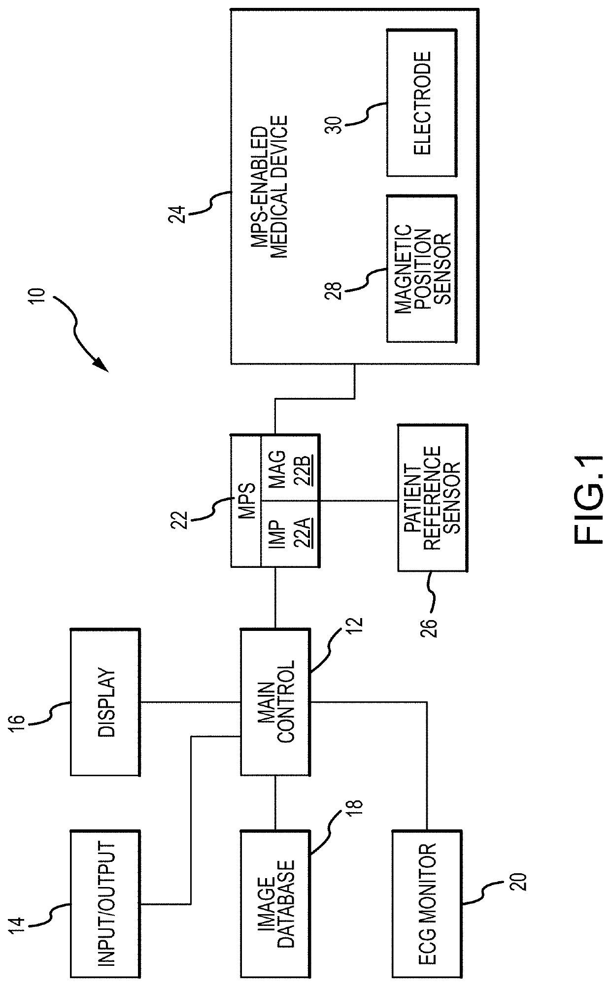
[0056]Referring now to the drawings wherein like reference numerals are used to identify identical or similar components in the various views, FIG. 1 is a diagrammatic view of a system 10 in which a medical device, such as a guidewire, catheter, introducer (e.g., sheath) incorporating a magnetic position sensor 28 and an electrode 30 may be used.

[0057]Before proceeding to a detailed description of the embodiments of the present disclosure, a description of an exemplary environment in which such devices and sensors may be used will first be set forth. With continued reference to FIG. 1, system 10, as depicted, includes a main electronic control unit 12 (e.g., a processor) having various input / output mechanisms 14, a display 16, an optional image database 18, an electrocardiogram (ECG) monitor 20, a localization system, such as a medical positioning system 22, a medical positioning system-enabled elongate medical device 24, a patient reference sensor 26, magnetic position sensor(s) 28...


PUM


Abstract

Provided herein are systems and methods for use in identifying location of electrodes of a catheter within a three-dimensional space. The systems and methods initially predict locations of physical electrodes and / or physical magnetic sensors of the catheter in the three-dimensional space. Impedance and / or magnetic responses are predicted for the predicted locations. Actual measurements / responses (e.g., measured responses) are then obtained for the physical electrodes and / or physical sensors. Based on the predicted responses and the measured responses, the systems and methods generate calculated locations of electrodes and / or sensors in the three-dimensional space. The systems and method utilize information from both the predicted responses and the measured responses to produce the calculated locations, which may have an accuracy that is greater than locations produced by either the predicted responses or the measured responses.

Description

CROSS REFERENCE[0001]The present application claims the benefit of the filing dates of: U.S. Provisional Application No. 62 / 756,941 having a filing date of Nov. 7, 2018; U.S. Provisional Application No. 62 / 756,915 having a filing date of Nov. 7, 2018; U.S. Provisional Application No. 62 / 756,926 having a filing date of Nov. 7, 2018; U.S. Provisional Application No. 62 / 756,931 having a filing date of Nov. 7, 2018; and U.S. Provisional Application No. 62 / 756,936 having a filing date of Nov. 7, 2018 the entire contents of each of which is incorporated herein by reference.BACKGROUNDa. Field[0002]The present disclosure relates generally to locating a medical device in a patient reference frame using a medical device model that estimates the shape of a medical device in the patient frame of reference in conjunction with measurements from impedance electrodes and magnetic sensors of the medical device.b. Background[0003]Various systems are known for determining the position and orientation ...

Claims


Application Information

Patent Timeline
IPC IPC(8): A61B5/06A61B5/00
CPCA61B5/062A61B5/725A61B5/068A61B5/6852
Inventor HILL, ANTHONY D.MALININ, YURIYTHOMPSON, CABLERYBNIKOV, SILVINIAYORESH, MAXIMSUDARSKY, ODED
Owner ST JUDE MEDICAL CARDILOGY DIV INC
Learn More