
Wind Energy System and Method for Controlling a Wind Power System

a technology of wind energy system and wind power system, which is applied in the direction of wind energy generation, mechanical equipment, machines/engines, etc., can solve the problems of high level of maintenance and service required, and the power that can be delivered to another electrical system is significantly reduced, so as to increase the risk of damage to electrical equipment and increase the deliverable power

Pending Publication Date: 2020-04-30
INNOGY SE
View PDF0 Cites 6 Cited by
  • Summary
  • Abstract
  • Description
  • Claims
  • Application Information

AI Technical Summary

Benefits of technology

This patent application describes a wind energy system that can increase the amount of power it can deliver without causing damage to electrical equipment. This is achieved through a condition detecting device that can measure the electrical parameters of the system. By making use of the detected conditions, the system can adjust its power output to maximize the amount of energy it can provide without exceeding the limits of the equipment. The system also uses a stationary approach to control the power and current, which makes it simpler and faster to implement. The condition detecting device can include a switching condition evaluating module that determines the electrical topology of the system based on the switching states of electrical switching devices. This improves the control of the system as it allows for individual control of each wind turbine with its own power set point.

Problems solved by technology

In particular, it is concern, to reduce the high level of maintenance and servicing required due to the special location at sea and the associated difficulty of access to the site.
However, the power that can be delivered to another electrical system is significantly reduced.

Method used


Image

  • Wind Energy System and Method for Controlling a Wind Power System
  • Wind Energy System and Method for Controlling a Wind Power System
  • Wind Energy System and Method for Controlling a Wind Power System

Examples


Embodiment Construction

[0047]In the following, the same reference signs are used for the same elements.

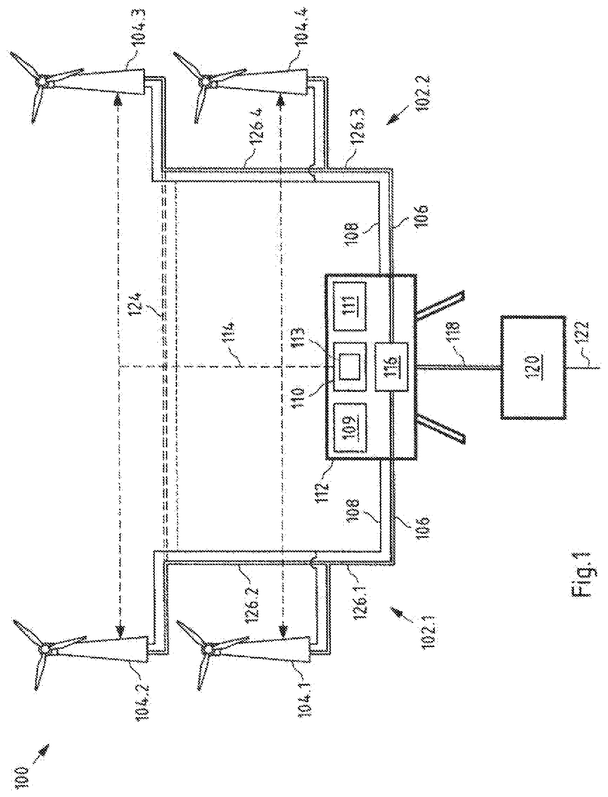
[0048]FIG. 1 shows a schematic view of an embodiment of a wind energy system 100 according to the present application. The shown wind energy system 100 is in particular an offshore wind energy system 100. The offshore wind energy system 100 comprises a plurality of wind energy devices 104, 112 and 120. In particular, an offshore transformer station 112 is arranged. A plurality of wind turbines are electrically connected to the offshore transformer station 112 via a cable network 106, in particular a transformer device 116 of the offshore transformer station 112. The cable network 106 comprises a plurality of submarine cables arranged between different wind turbines 104.1 to 104.4. In addition, the cable network comprises at least one submarine cable between the offshore transformer station 112 and an onshore terminal station 120. The onshore terminal station 120 serves, among other things, as an electric...


PUM


Abstract

Provided are embodiments of a wind energy system. The system includes a plurality of wind turbines connected to at least one cable network. The cable network is configured to transmit the electrical power fed-in by the connected wind turbines. The system also includes at least one control apparatus configured to control the power fed into the cable network by at least one of the wind turbine by providing at least one power set point. At least one temperature detecting device is configured to detect the temperature of the cable network. At least one condition detecting device is configured to detect the condition of the wind energy system, and the control apparatus includes at least one control device configured to determine the power set point based on the detected temperature and the detected condition.

Description

CROSS-REFERENCE TO RELATED PATENT APPLICATIONS[0001]This patent application is a continuation of PCT / EP2018 / 064842, filed Jun. 6, 2018, which claims priority to German Application No. 10 2017 114 309.2, filed Jun. 28, 2017, the entire teachings and disclosure of which are incorporated herein by reference thereto.FIELD[0002]The application relates to a wind energy system, in particular an offshore wind energy system, comprising a plurality of wind turbines connected to at least one cable network, wherein the cable network is configured to transmit the electrical power supplied by the connected wind turbines, at least one control apparatus configured to control the power supplied to the cable network by at least one of the wind turbine by providing at least one power set point. In addition, the application relates to a control apparatus and a method for controlling a wind turbine.BACKGROUND[0003]The demand for electrical energy from renewable sources is rising steadily. One of the ava...

Claims


Application Information

Patent Timeline
Patent Type & Authority Applications(United States)
IPC IPC(8): F03D9/25F03D7/02F03D17/00
CPCF03D17/00F03D7/028F03D9/257F05B2270/1033F05B2270/3032F05B2270/335F03D9/255Y02E10/72
Inventor FELTES, CHRISTIANJAHN, CHRISTIANTHOMSEN, NILSRUNGE, JÖRN
Owner INNOGY SE
Learn More