
Method and arrangement for controlling a dewatering process

a technology of dewatering process and control method, which is applied in the direction of sedimentation settling tank, separation process, instruments, etc., can solve the problems of process control, affecting the performance of subsequent processes, and operating personnel from running the separation device in an efficient manner, so as to reduce the variation of process output, reduce the use of process chemicals, and increase productivity

Active Publication Date: 2020-04-30
METSO OUTOTEC (FINLAND) OY
View PDF0 Cites 5 Cited by
  • Summary
  • Abstract
  • Description
  • Claims
  • Application Information

AI Technical Summary

Benefits of technology

The present invention aims to reduce variations in the process output, decrease the usage of process chemicals, increase productivity, and reduce the time and resources required for manual operations. This is achieved by using a predictive multivariable model that can optimize the determination of control parameters for the dewatering process. This approach allows for the definition of process constraints in a new way, which can improve the efficiency of the process in various ways depending on the operating parameters and process constraints used.

Problems solved by technology

There are various problems preventing the operators from running the separation devices in an efficient manner.
Long process response times, long process delays and variation in the incoming mass flow make process control challenging.
This, in turn, may affect the performance of subsequent processes, i.e. filtering, tailings handling, and water re-circulation systems.
Slow response dynamics and cross actions between the controlled parameters can make the tuning of the PI-loops very challenging and require compromises between system robustness and desired speed of response.
In practical operating situations, this may result in need for repeated operator intervention and the controller being run either totally or partially in manual mode.
In addition to reduced quality and increased variation in process outputs, also the expenditure of process chemicals may be increased.

Method used


Image

  • Method and arrangement for controlling a dewatering process
  • Method and arrangement for controlling a dewatering process
  • Method and arrangement for controlling a dewatering process

Examples


Embodiment Construction

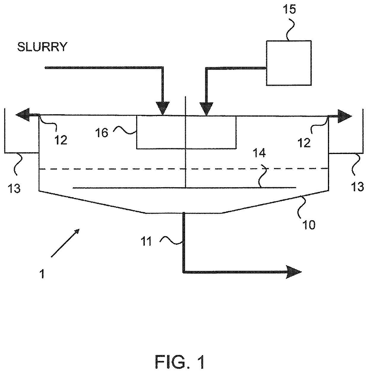
[0016]Reference will now be made in detail to the embodiments of the present disclosure, examples of which are illustrated in the accompanying drawings.

[0017]The dewatering process according to the disclosure may be considered as a separation process, in which fluid is separated from solid matter. The material to be separated in the process may be called process slurry. Typically, the carrier fluid is water but other fluids may also be used. In particular, the carrier fluid may comprise a mixture of water and process chemicals including for example acid / alkaline, metals, salts and others. To accelerate the sedimentation process, chemicals such as flocculants or coagulants may be used.

[0018]Several zones or layers of material having different overall densities gradually form within the tank. At the bottom of the tank, the pulp forms a relatively dense zone of compacted pulp or solids that are frequently in the form of networked aggregates (i.e. the pulp aggregates are in continuous c...


PUM

PropertyMeasurementUnit
Timeaaaaaaaaaa
Flow rateaaaaaaaaaa
Feed rateaaaaaaaaaa

Abstract

An arrangement and a method for controlling a dewatering process including measuring values representing operating parameters of the gravitational sedimentation device and using the values as input values for a predictive multivariable model for predicting an operating state of the gravitational sedimentation device. The disclosure further relates to obtaining reference values for the operating parameters, determining at least one predicted output for an operating parameter of the gravitational sedimentation device, and comparing the predicted output to at the reference values to determine control values that will affect changes in operation of the gravitational sedimentation device.

Description

FIELD OF THE INVENTION[0001]The present disclosure relates to a method and an arrangement for controlling a dewatering process in a gravitational sedimentation device. In particular, the present disclosure relates to multivariable control of a gravitational sedimentation process.BACKGROUND OF THE INVENTION[0002]Separation devices, such as thickeners, clarifiers and concentrators, are used for separating solids from suspensions (typically containing solids suspended in a liquid) and are often found in the mining, mineral processing, food processing, sugar refining, water treatment, sewage treatment, and other such industries. These devices typically comprise a tank in which solids are deposited from a suspension or solution and settle toward the bottom as pulp or sludge to be drawn off from below and recovered. A dilute liquor of lower relative density is displaced toward the top of the tank, for removal via an overflow launder. The suspension to be thickened is initially fed through...

Claims


Application Information

Patent Timeline
IPC IPC(8): B01D21/30G05B13/04B01D21/08B01D21/01B01D21/06B01D21/32B01D21/34C02F1/52
CPCG05B13/048C02F2209/10C02F2209/11B01D21/302C02F2209/40B01D21/32B01D21/14B01D21/01B01D21/34B01D21/08C02F1/5281G05B13/042C02F2209/42B01D21/30B01D21/02B01D21/06B01D2221/04C02F2001/007G05B13/044B01D21/2427G05B13/04G05B15/00B01D21/0006B01D21/0042B01D21/0087G01B15/00G01N1/20G05B13/041C02F1/52
Inventor KOSONEN, MIKAKAUVOSAARI, SAKARI
Owner METSO OUTOTEC (FINLAND) OY
Learn More