
Cosmetic apparatus

a technology of cosmetic equipment and guiding head, which is applied in the direction of packaging foodstuffs, packaging goods, transportation and packaging, etc., can solve the problems of user discomfort in operation, unsatisfactory cotton pad, limited guiding face area, etc., and achieve the effect of enhancing combination stability and beauty accessories

Inactive Publication Date: 2020-04-23
ADC MEDICAL LTD
View PDF2 Cites 0 Cited by
  • Summary
  • Abstract
  • Description
  • Claims
  • Application Information

AI Technical Summary

Benefits of technology

The patent is about a cosmetic device that makes it easier to apply makeup with other beauty tools. The device makes the makeup and tools mix better, which makes it easier to apply and create the desired look.

Problems solved by technology

However, the fixed ring is pressed and fixed with the assembly surface of the body, and the assembly surface is connected with and mounted around the guiding head, which makes an area of the guiding face of the guiding head quite limited.
Therefore, the cotton pad is unsmooth, which causes a user to feel uncomfortable in operation.
Therefore, a positioning effect of the cotton pad is poor when the conventional cosmetic apparatus is in use.
Furthermore, if the thickness of the cotton pad is too thick, the fixed ring may not be pressed and fixed around the guiding head.
That is, the applicable thickness of the cotton pad is limited.

Method used


Image

  • Cosmetic apparatus
  • Cosmetic apparatus
  • Cosmetic apparatus

Examples


first embodiment

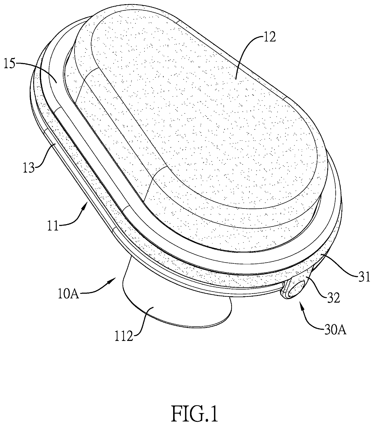
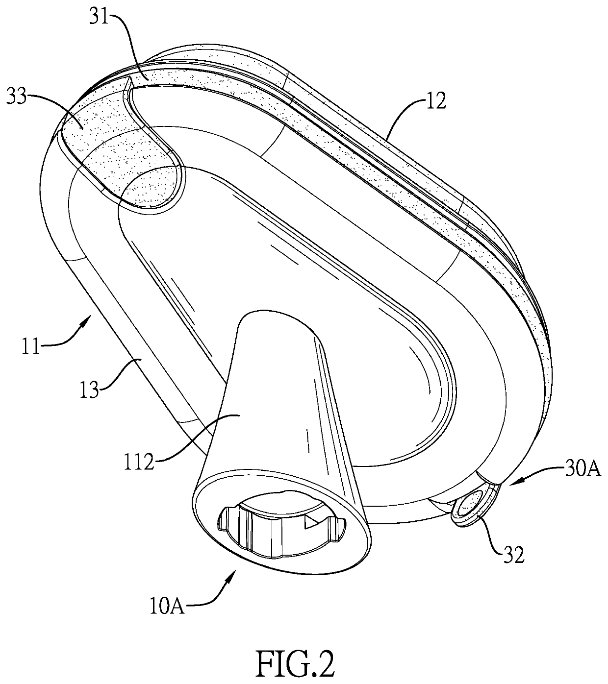
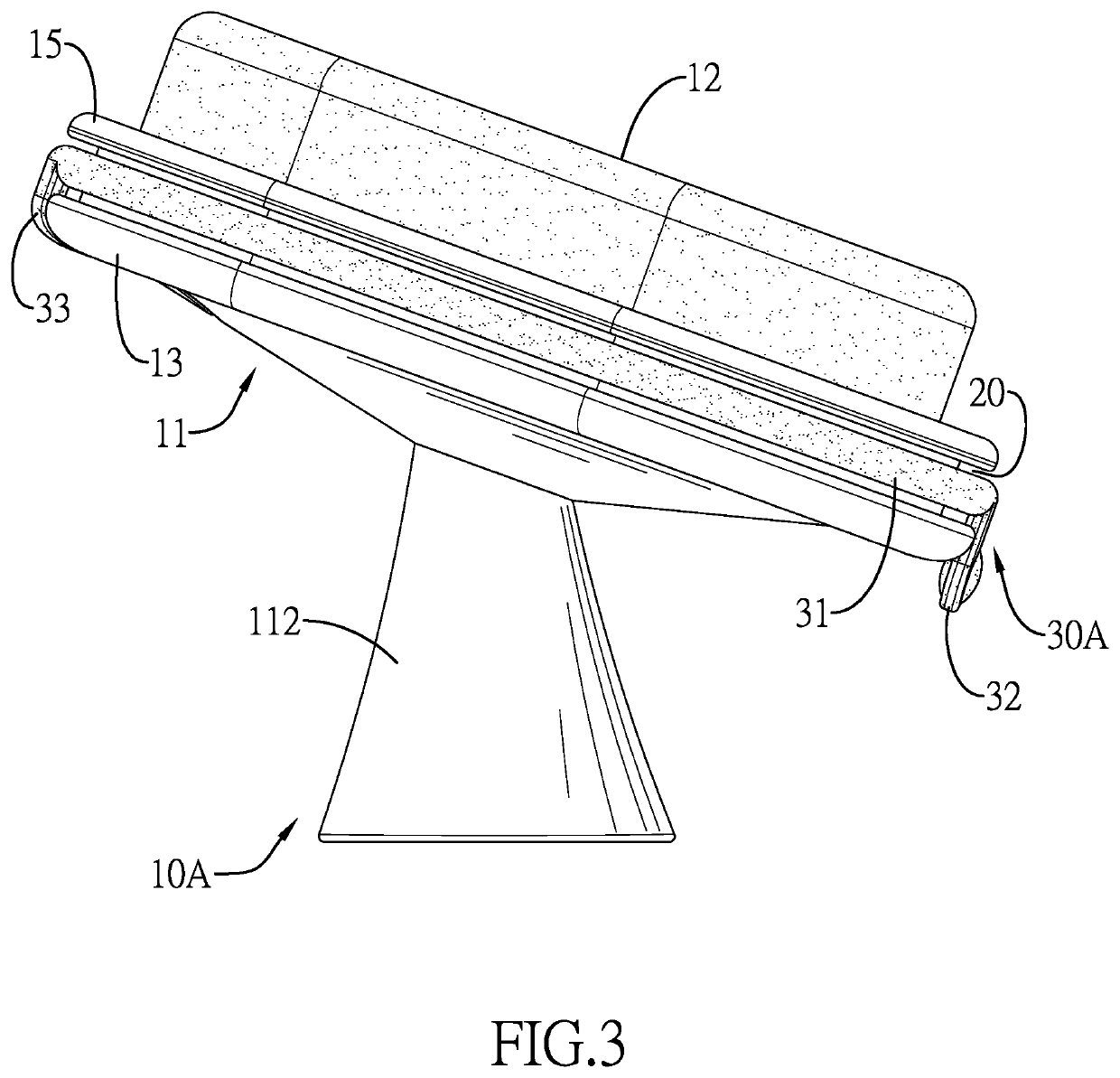
[0024]With reference to FIGS. 1 to 4, a cosmetic apparatus in accordance with the present invention comprises an operating piece 10A, a recess 20, and a holder 30A.

[0025]The operating piece 10A has a seat 11 and a cosmetic head 12. The cosmetic head 12 is mounted on a top surface of the seat 11. With reference to FIG. 4, the cosmetic head 12 is a powder puff head. The seat 11 has a bottom board 13, a surrounding wall 14, and a positioning ring 15. The surrounding wall 14 is formed at a top surface of the bottom board 13, and the cosmetic head 12 is enclosed by the surrounding wall 14. The positioning ring 15 is buckled with the surrounding wall 14 and holds the cosmetic head 12 in position. The positioning ring 15 extends out of an outer surface of the surrounding wall 14 and faces the bottom board 13.

[0026]The recess 20 is formed around an outer surface of the seat 11, and is adjacent to a junction of the seat 11 and the cosmetic head 12. With reference to FIG. 4, the recess 20 is ...

second embodiment

[0029]With reference to FIGS. 8 to 11, a cosmetic apparatus in accordance with the present invention comprises an operating piece 10D, a recess 20, and a holder 30D.

[0030]The operating piece 10D has a seat 11 and a cosmetic head 12. The cosmetic head 12 is detachably mounted on the seat 11. With reference to FIG. 8, the cosmetic head 12 is replaceable. The cosmetic head 12 can be a make-up remover sponge, a powder puff, a cleansing brush, or an infusion head. With reference to FIGS. 9 and 14, the seat 11 has a connecting recess 113 and two sliding recesses 114. The connecting recess 113 is formed in a top surface of the seat 11. The two sliding recesses 114 are formed in the top surface of the seat 11 and are arranged at a spaced interval. The two sliding recesses 114 communicate with the connecting recess 113. Each sliding recess 114 has a first section 115 and a second section 116. The first section 115 is formed in the top surface of the seat 11 in a vertical direction. The secon...


PUM


Abstract

A cosmetic apparatus has an operating piece, a recess, and a holder. The operating piece has a seat and a cosmetic head. The cosmetic head is mounted on the seat. The recess is formed around an outer surface of the seat, and is adjacent to a junction of the seat and the cosmetic head. The holder is made of silicon, is detachably mounted around the operating piece, and is inserted into the recess. The holder has a loop and a tab. The loop is mounted around the operating piece, and is inserted into the recess. The tab is formed at the loop and protrudes from a bottom surface of the seat.

Description

BACKGROUND OF THE INVENTION1. Field of the Invention[0001]The invention relates to a cosmetic apparatus, and more particularly to a cosmetic apparatus which may enhance combination stability with beauty accessories.2. Description of Related Art[0002]A conventional cosmetic apparatus has infusion and detoxification functions. The infusion function may assist the skin in absorbing skincare products. The detoxification function may assist the pores in discharging dirt. The conventional cosmetic apparatus has a body, a guiding head, and a fixed ring. The guiding head is mounted at and protrudes from a top surface of the body. The guiding head has a distal end and a guiding face. The guiding face is formed at the distal end of the guiding head. Furthermore, the body has an assembly surface. The assembly surface is formed on the top surface of the body. The assembly surface is connected with and mounted around the guiding head. The fixed ring is detachably mounted around the assembly surf...

Claims


Application Information

Patent Timeline
Patent Type & Authority Applications(United States)
IPC IPC(8): A45D34/04A45D33/34A46B5/00
CPCA45D34/042A46B5/0095A45D33/34A45D33/36A45D34/04A45D2200/1018A45D2200/1063A46B2200/1046
Inventor WONG, YEE KEUNG KENT
Owner ADC MEDICAL LTD
Learn More