Coil component

a coil and component technology, applied in the field of coil components, can solve the problems of insufficient order, metal inductance, and inability to be used in equipment, and achieve the effect of small leakage magnetic flux and excellent dc superposition characteristics

Active Publication Date: 2020-04-16
MURATA MFG CO LTD
View PDF11 Cites 0 Cited by
  • Summary
  • Abstract
  • Description
  • Claims
  • Application Information

AI Technical Summary

Benefits of technology

The present disclosure provides a coil component with good DC superposition characteristics and reduced leakage magnetic flux. This is achieved by adding a non-magnetic layer in the body of the coil component, which does not extend through the entire body. The non-magnetic layer helps to improve the performance of the coil component by enhancing its desired magnetic properties.

Problems solved by technology

As a small-sized inductor, a ferrite inductor that uses a ferrite material for a magnetic layer is known, but, because the ferrite inductor does not have sufficient DC superposition characteristics, is not suitable in some cases for use in equipment in which a large current is applied.
However, a conventional metal inductor described in Japanese Patent Application Laid-Open No. 2015-7993, i.e., a coil component including a body including a metal magnetic body and a coil conductor embedded in the body, cannot necessarily be said to be sufficient in order to meet gradually increasing demand of increasing the DC superposition characteristics.

Method used


Image

  • Coil component
  • Coil component
  • Coil component

Examples


Embodiment Construction

[0018]The coil component of the present disclosure is described in detail with reference to the drawings. However, the shape, the arrangement, and the like of constituent elements of the coil component of the present embodiment are not limited to the illustrated examples.

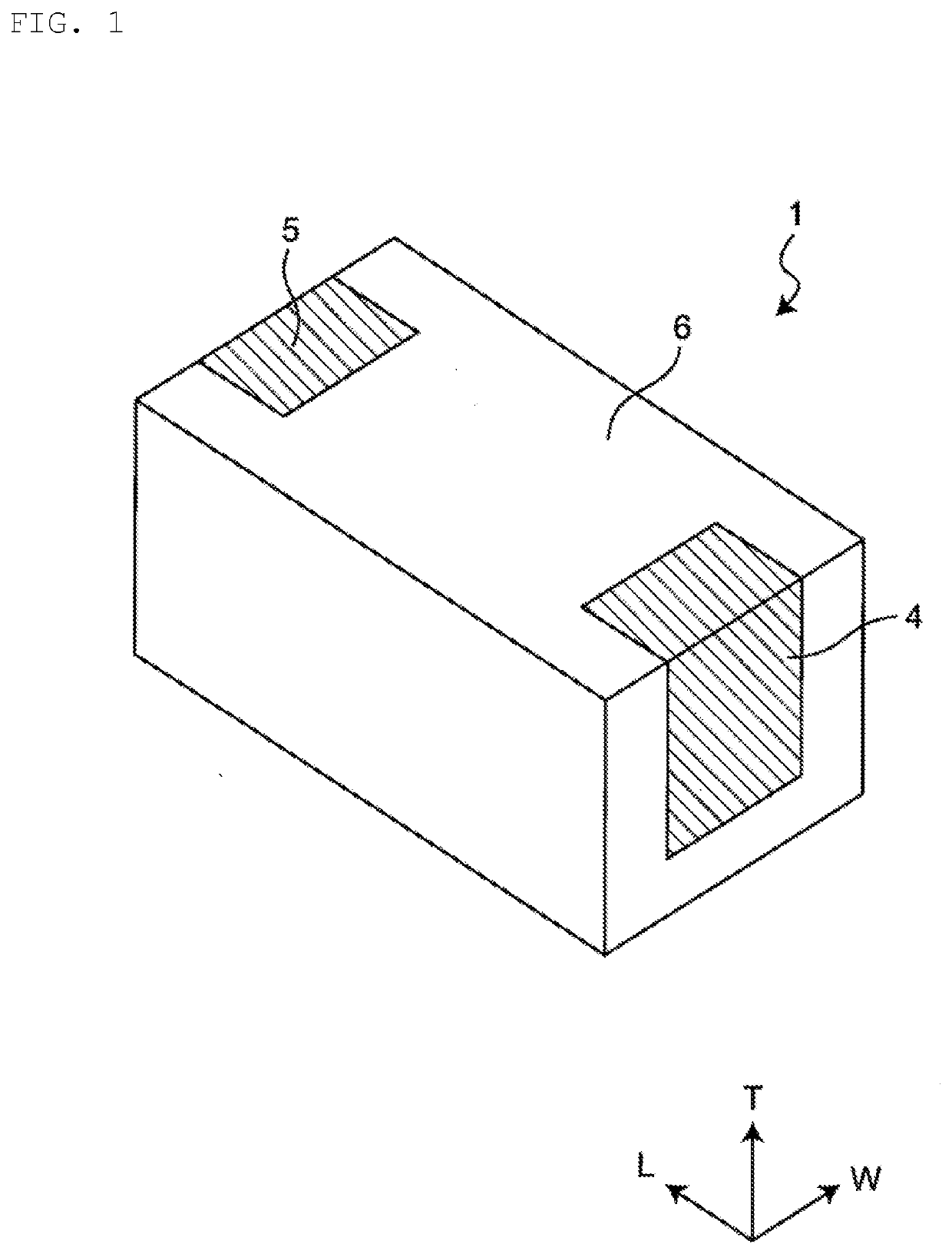
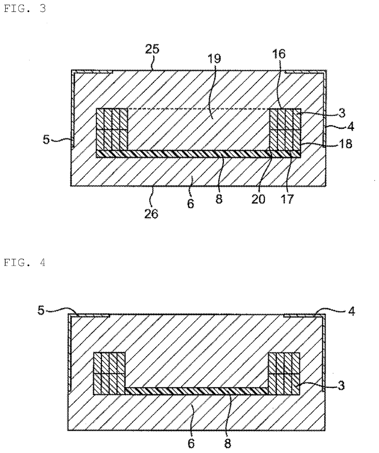
[0019]A perspective view of a coil component 1 of the present embodiment is schematically illustrated in FIG. 1, a perspective view of a body 2 of the coil component 1 is illustrated in FIG. 2, and a cross-sectional view of the coil component 1 is illustrated in FIG. 3.

[0020]As illustrated in FIGS. 1 to 3, the coil component 1 of the present embodiment has a substantially rectangular parallelepiped shape. The coil component 1 substantially includes the body 2, the coil conductor 3 embedded in the body 2, and outer electrodes 4 and 5. Here, regarding the body 2, the right and left side surfaces in the drawing of FIG. 3 are called “end surfaces,” the upper side surface in the drawing is called a “top surface,” the low...


PUM


Abstract

A coil component includes a body and a coil conductor embedded in the body. The body includes a magnetic layer and a non-magnetic layer. The magnetic layer is formed of a composite material including a metal particle and a resin material, and the non-magnetic layer is arranged not to extend through a winding portion of the coil conductor or not to entirely extend through the body.

Description

CROSS-REFERENCE TO RELATED APPLICATIONS[0001]This application claims benefit of priority to International Patent Application No. PCT / JP2018 / 020705, filed May 30, 2018, and to Japanese Patent Application No. 2017-119824, filed Jun. 19, 2017, the entire contents of each are incorporated herein by reference.BACKGROUNDTechnical Field[0002]The present disclosure relates to a coil component, and more specifically to a coil component including a body and a coil conductor embedded in the body.Background Art[0003]Conventionally, a coil component has been used as a power inductor in a DC / DC converter circuit or the like. Because of a reduction in size and an increase in current of electronic equipment in recent years, power inductors also require a reduction in size and an increase in current. As a small-sized inductor, a ferrite inductor that uses a ferrite material for a magnetic layer is known, but, because the ferrite inductor does not have sufficient DC superposition characteristics, is ...

Claims


Application Information

Patent Timeline
IPC IPC(8): H01F27/28H01F27/32H01F27/29H01F27/245H01F41/04H01F41/02
CPCH01F27/29H01F27/2823H01F27/245H01F41/0206H01F27/32H01F41/04H01F17/0006H01F2017/048H01F2017/0066H01F3/10H01F17/04
Inventor SHIMIZU, NORIKOSHINOHARA, GOTASUGIYAMA, MIKITOYONEMURA, MARI
Owner MURATA MFG CO LTD
Why Eureka
Try Eureka