
Pellet smoker

a pellet smoker and pellet technology, applied in the field of solid fuel cooking, can solve the problems of difficult to obtain such high thermal intensities, the cost of scaling up the auger drive, the delivery of combustion air fans, the structure of the firepit, etc., and achieve the effect of convenient access

Active Publication Date: 2020-04-16
W C BRADLEY CO
View PDF0 Cites 10 Cited by
  • Summary
  • Abstract
  • Description
  • Claims
  • Application Information

AI Technical Summary

Benefits of technology

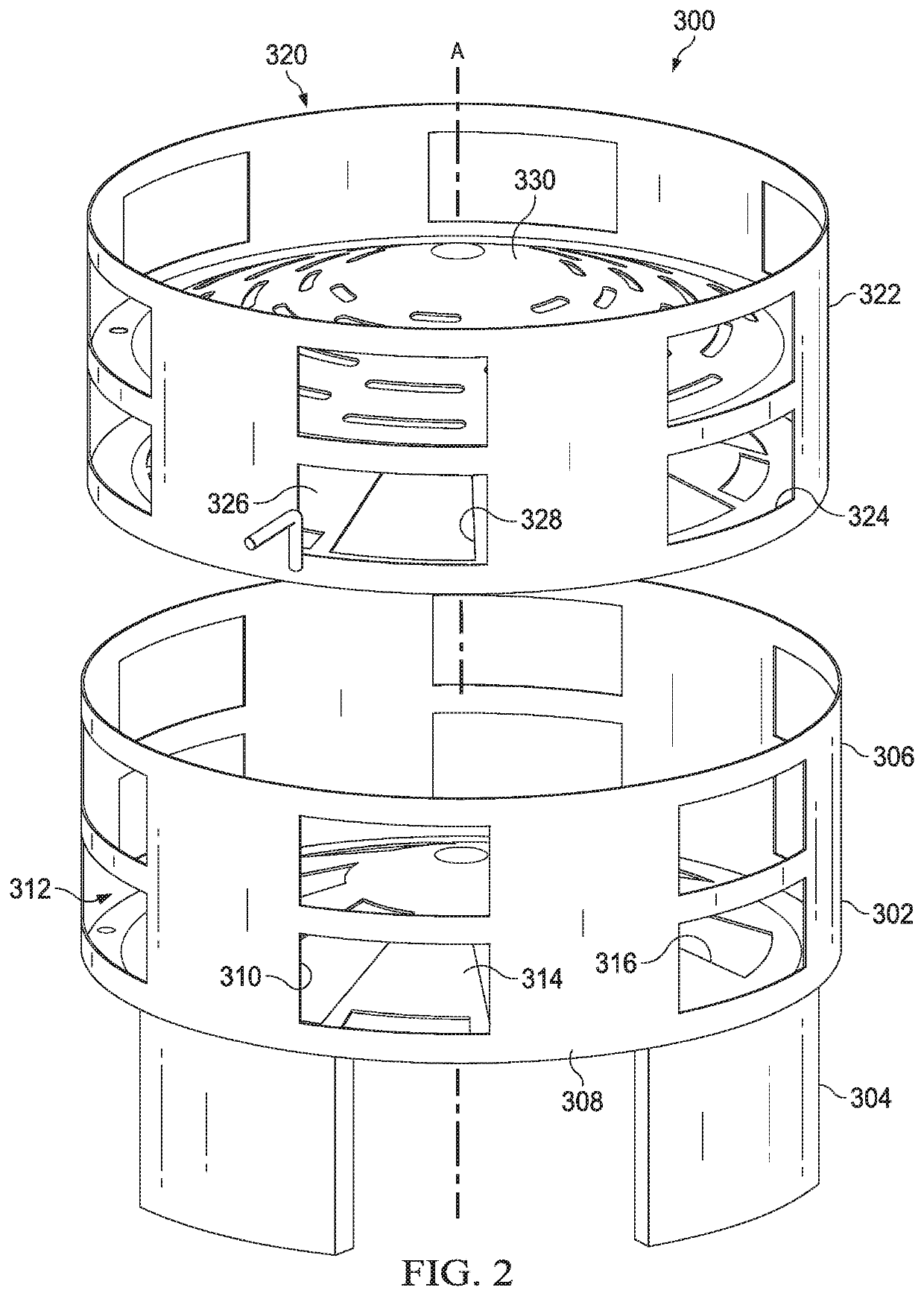
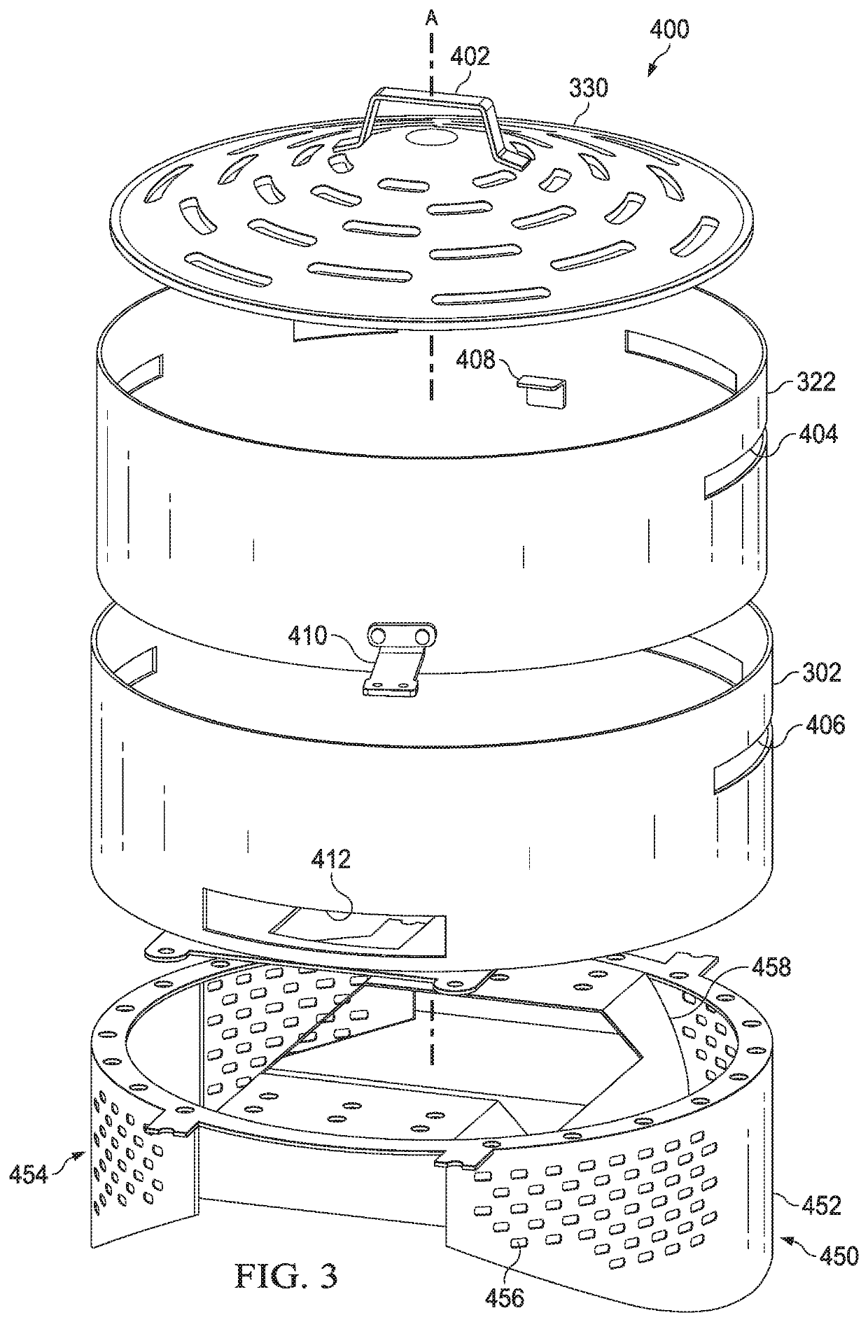
The present invention relates to a dual component baffle structure for a smoker that allows for controlled flow of gases through the baffle structure. The baffle structure has floor and upright sidewall openings that can be selected or deselected by rotation of the two vertical components relative to each other. The baffle structure can be supported over a firepot in a firebox and interposes the cooking grate and the heat source to concentrate heat on a high temperature zone of the cooking grate when the openings are selected. The invention also includes a cooking grill with a baffle structure that disperses heat away from the heat source to a larger area on the cooking grate when the openings are closed.

Problems solved by technology

Using appliances having a relatively large cooking area (common in the marketplace) it may become very difficult to obtain such higher thermal intensities as may be desired for grilling over short periods of time (on the order of minutes) simply by upsizing, or by more rapidly running the auger feed from the pellet hopper.
Such difficulty is, first of all, based on the problem of evenly distributing heat from a concentrated heat source (e.g., a single firepot), to a large, typically rectangular, cooking area without absorbing or losing too much heat in the baffle structure necessary to accomplish this.
A second difficulty, from a commercial point of view, is the expense of scaling up the auger drive and combustion air fan delivery and firepot structure.
Also, a large-scale, high thermal intensity, fire systems struggle delivering the cool smoking feature in currently available designs.
Thus, it has remained the case that most such pellet appliances described do not perform well for grilling, particularly in providing high cooking grate temperatures to create searing action on the exterior of the food.

Method used


Image

  • Pellet smoker
  • Pellet smoker
  • Pellet smoker

Examples


Embodiment Construction

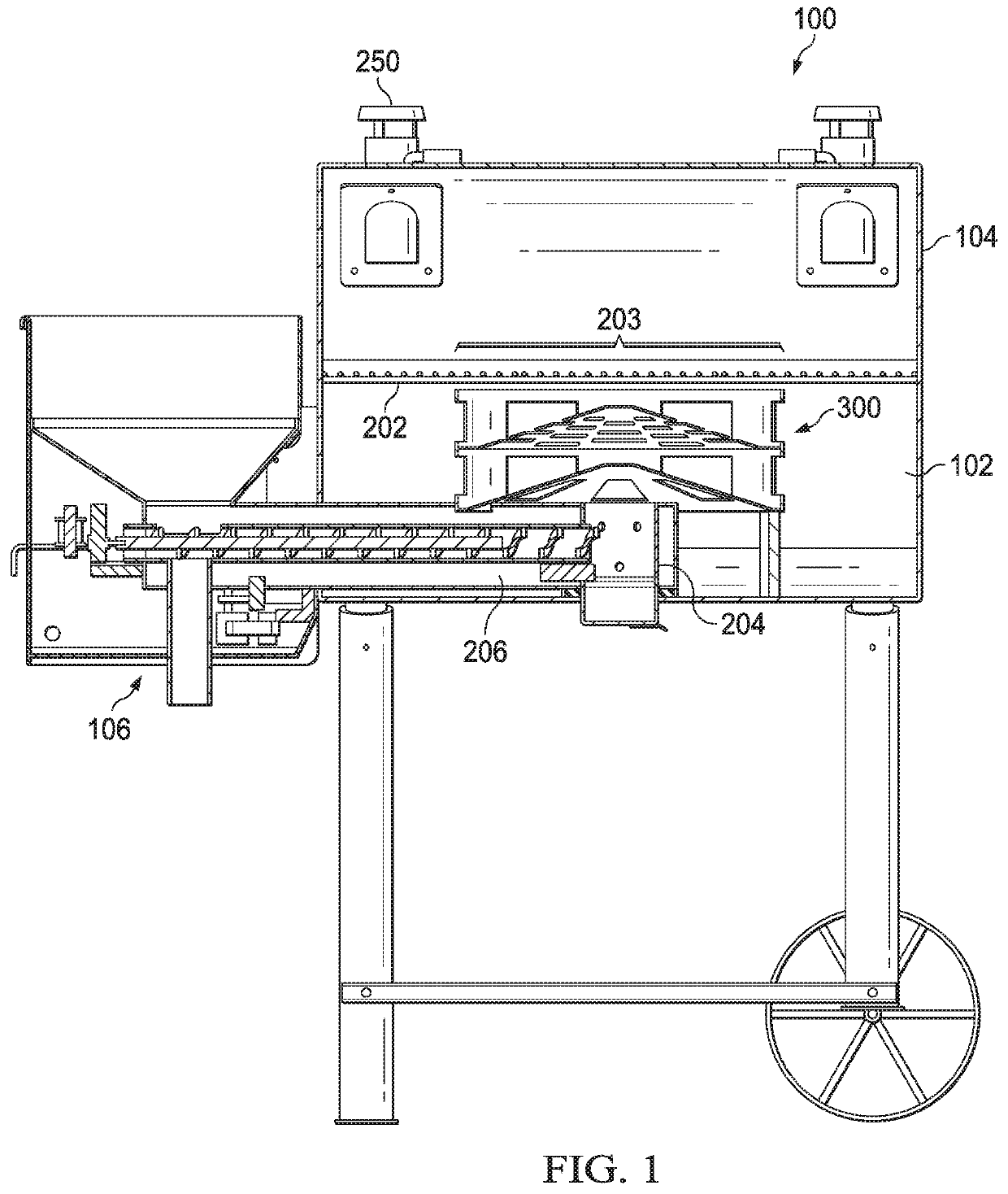
[0021]Referring now to FIG. 1, a cutaway view of a smoker according to aspects of the present disclosure is shown. The smoker 100 may comprise a firebox 102 with an openable lid 104. The lid 104 may be hinged and have a handle for opening and closing as well as one or more flues or vents 250. A pellet feeding hopper system 106 can be seen where a user feeds fuel pellets for auguring into a firepot 204 for combustion. A vent duct 206 may provide combustion air to the firepot 204, possibly under positive pressure. Both fuel and air supply may be user controllable for the amount of heat and / or smoke produced.

[0022]A cooking grate 202 may be provided within the firebox 102 on which food items rest while being cooked. A baffle structure 300 interposes the firepot 204 and the cooking grate 202 as described herein. The baffle structure 300 can be used to control the delivery of heat and combustion products to provide a diffuse delivery throughout the smoker 100 and cooking grate 202. It ma...


PUM


Abstract

A floor and an upright sidewall formed from two vertically coaxial components, each component having a floor baffle with a plurality of floor openings defined therein, each floor retained within a respective upright sidewall with a plurality of sidewall openings defined therein. The floor openings and the sidewall openings cooperate between the two coaxial components such that flow of gases through the floor and upright sidewall of the baffle structure is controlled by rotation of the two vertically coaxial components relative to one another.

Description

CROSS-REFERENCE TO RELATED CASES[0001]This application claims the benefit of U.S. provisional patent application Ser. No. 62 / 745,050, filed on Oct. 12, 2018, and incorporates such provisional application by reference into this disclosure as if fully set out at this point.FIELD OF THE INVENTION[0002]This disclosure relates to solid fuel cooking in general and, more particularly, to systems for cooking using solid fuel pellets.BACKGROUND OF THE INVENTION[0003]Prior outdoor wood pellet fired cooking and smoking appliances are described, among other places, in U.S. Pat. Nos. 4,823,684 and 5,251,607, both to Joseph Traeger, et al. Some improvements and variations of these products may have been made but their essential principal of operation remains the same. An electrically driven auger transports small compressed wood pellets from an exterior hopper to a combustion chamber or firepot (typically cylindrical and / or having an open top). The combustion chamber or firepot is supplied with c...

Claims


Application Information

Patent Timeline
IPC IPC(8): F23B30/00A47J37/07F24B1/02A23B4/052
CPCA47J37/0704A23B4/052F24B1/024F23B2700/013F23B7/002F23B2700/037F23B1/38F24B1/1895F24B1/207
Inventor RAHMANI, RAMIN KHOSRAVIHAMILTON, ANTHONYROBERTS, BRUCEAHMED, MALLIKABDALLAH, SLEIMANGILLISPIE, BRADCORSO, DAN
Owner W C BRADLEY CO
Learn More