Tissue removal device

Inactive Publication Date: 2020-04-09
SABETI MIKE
View PDF0 Cites 0 Cited by
  • Summary
  • Abstract
  • Description
  • Claims
  • Application Information

AI Technical Summary

Benefits of technology

The surgical device described in this patent helps hold and remove tissue from a surgery without causing it to be displaced. It is particularly useful for removing granulation tissue from a periodontal or endodontic surgery. It can also remove tissue that is difficult to access or resistant to separation from bone. The device quickly and easily removes granulation tissue while keeping the surgery area blood-free. This helps to quickly stop bleeding caused by the highly vascularized granulation tissue.

Problems solved by technology

The presence of abundant granulation tissue may contribute to failure in the treatment of acute infections.
For example, a removal of irritant or diseased tissue associated with the root apex is needed in periradicular surgery to achieve optimal healing In some cases, after a tooth extraction, the granulation tissue that is formed in the extraction socket prevents the extraction socket from healing and leads to severe pain.
The removal of the granulation tissue by a curette is a time consuming and tedious process, which can be stressful and frustrating for the patient as well as the surgeon depending upon the number of affected teeth.
Moreover, during most surgical procedures in medical and dental practice, the tissue to be removed is often present in a location that is difficult to access.
For example, in periodontal operations, the granulation tissue is recessed far below the gingival line, in areas of bone deterioration near the root of the tooth, thereby making it difficult to cut or scrape and remove the granulation tissue.
Furthermore, tough fibrotic tissue that is bound to the underlying bone or tissue that is resistant to separation from a bony crypt is difficult to remove.
Furthermore, when conventional tissue removal devices are used for removing granulation tissue, which is highly vascularized and therefore, bleeds profusely, the granulation tissue is typically displaced, making the granulation tissue difficult to remove and further making the process time consuming and tedious, which can be stressful and frustrating for the patient as well as the surgeon.

Method used


Image

  • Tissue removal device
  • Tissue removal device
  • Tissue removal device

Examples


Embodiment Construction

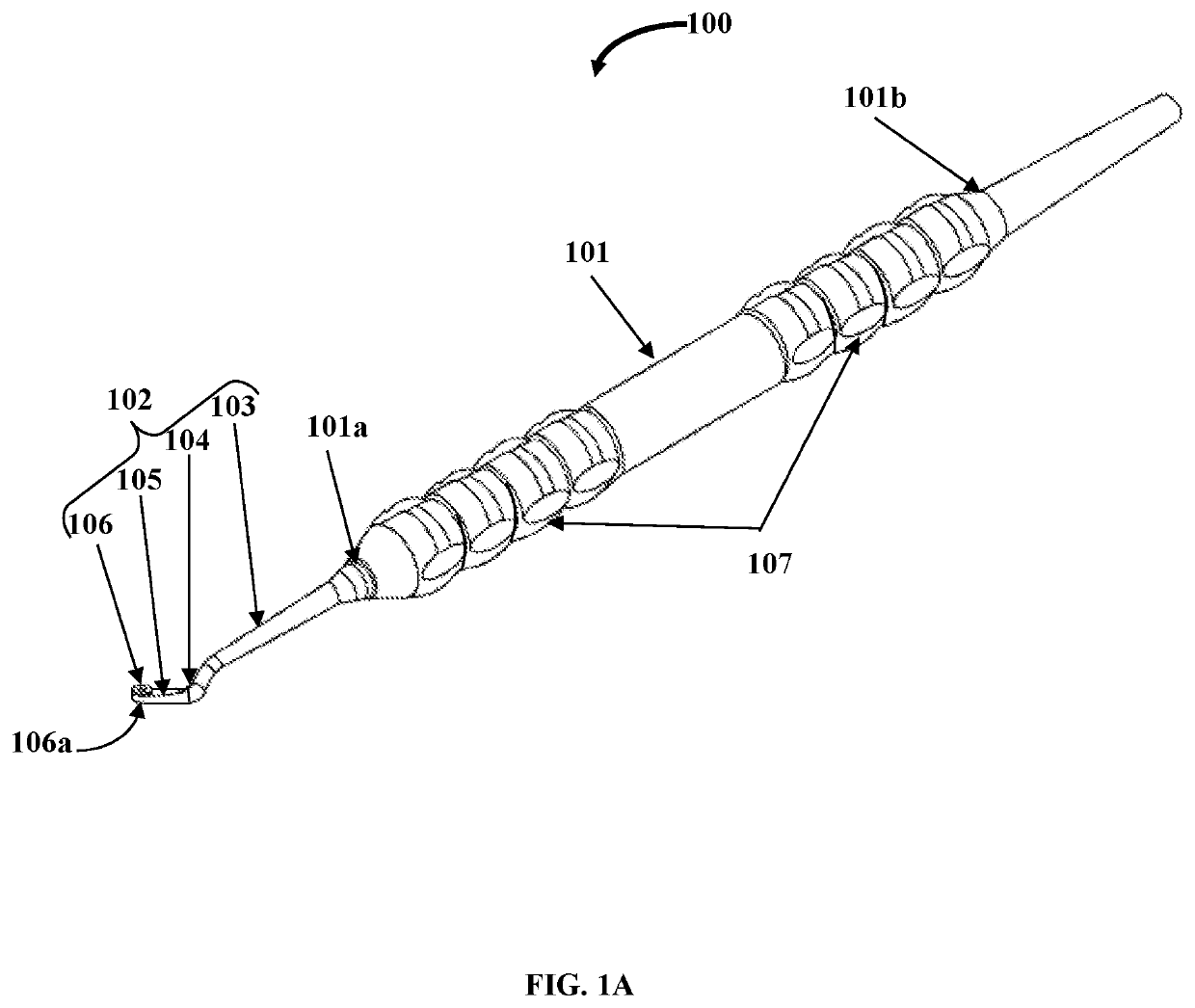
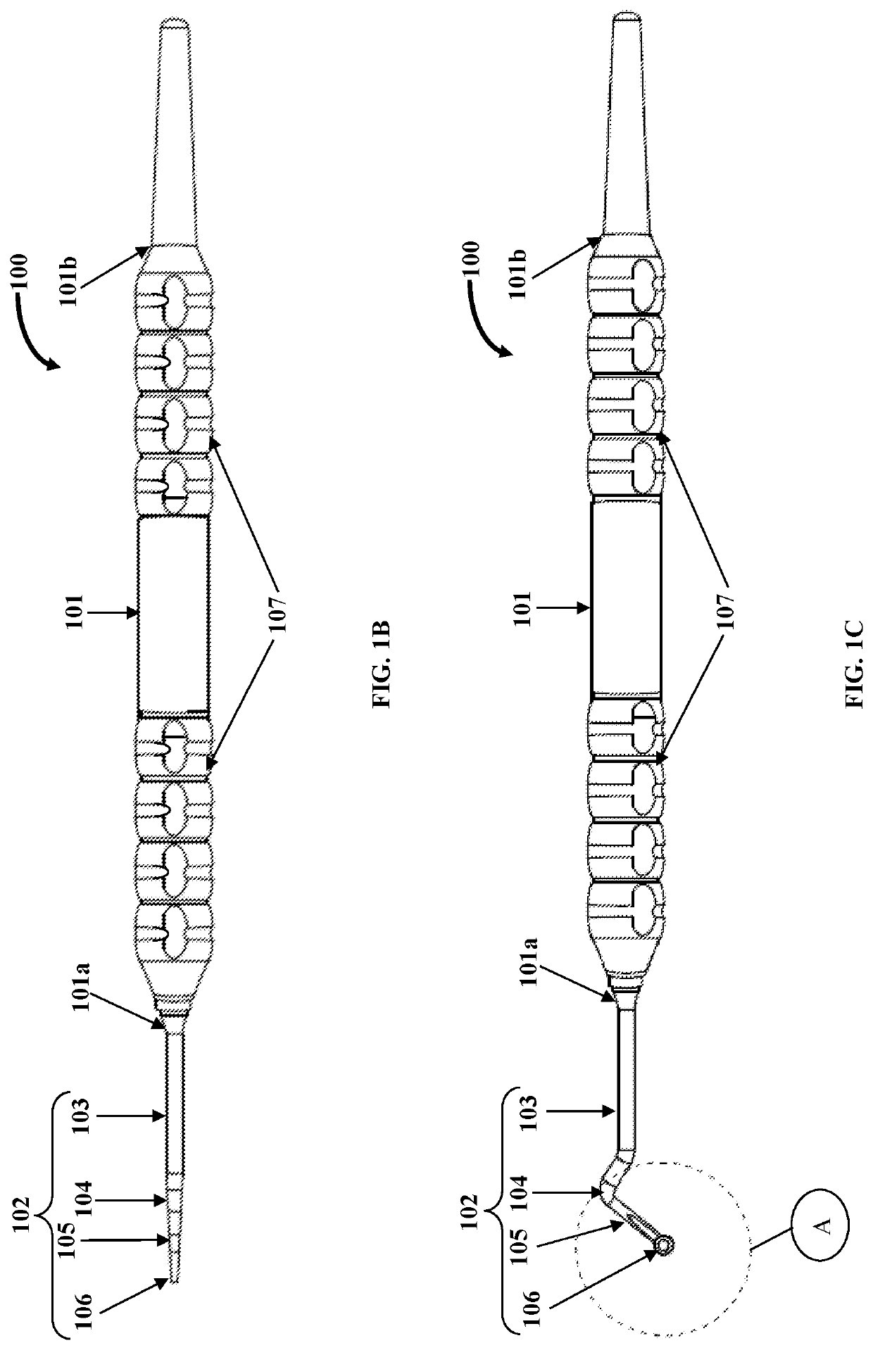
[0023]FIGS. 1A-1C exemplarily illustrate a top perspective view, a side elevation view, and a bottom plan view of a surgical device 100, also referred to as a “tissue removal device”, respectively, for removing target tissue and precluding the target tissue from being displaced during surgery. The target tissue comprises, for example, granulation tissue formed in wounds of dental structures comprising, for example, periodontal structures, endodontic structures, and extraction sockets. The surgical device 100 disclosed herein comprises a tubular handle 101 and a tissue removal member 102. The tubular handle 101 comprises a distal end 101a and a proximal end 101b as exemplarily illustrated in FIGS. 1A-1C. The tubular handle 101 is, for example, made of plastic. The tissue removal member 102 extends from the distal end 101a of the tubular handle 101. The tissue removal member 102 comprises a shank 103, an arcuate section 104, a shaft 105, and a loop receptacle 106 with a closed bottom ...


PUM


Abstract

A surgical device including a tubular handle and a tissue removal member for removing target tissue, for example, granulation tissue, is provided. The tissue removal member extends from a distal end or from both a proximal end and the distal end of the tubular handle. The tissue removal member includes a shank, an arcuate section, a shaft of a configurable length for reaching a surgical site, and a loop receptacle. The loop receptacle extended from a distal end of the shaft. has an annular section defining an opening and a closed bottom end. The annular section includes a circular cutting edge for contacting and drawing away target tissue from the surgical site. The opening of the loop receptacle receives and holds the target tissue drawn away from the surgical site, thereby precluding the target tissue from being displaced during a removal of the target tissue.

Description

BACKGROUNDTechnical Field[0001]The apparatus disclosed herein, in general, relates to a surgical instrument for removing tissue. More particularly, the apparatus disclosed herein relates to a tissue removal device for optimally holding and removing target tissue from a surgical site and precluding the target tissue from being displaced during surgery.Description of the Related Art[0002]Many surgical procedures, for example, periodontal procedures, endodontic procedures, dental procedures for extraction sockets, etc., require a surgical removal of tissue, for example, granulation tissue, from a surgical site of operation. Granulation tissue refers to connective tissue with microscopic blood vessels that form on wound surfaces during a healing process. Under certain conditions such as an infection or a local reaction to a chronically implanted, foreign material, granulation tissue grows uncontrollably and becomes vascular and secretive. The presence of abundant granulation tissue may ...

Claims


Application Information

Patent Timeline
IPC IPC(8): A61C3/02A61C5/42
CPCA61C3/02A61C5/42A61C5/40
Inventor SABETI, MIKE
Owner SABETI MIKE
Why Eureka
Try Eureka