
Robotic vehicle panel alignment system and process

Inactive Publication Date: 2007-02-15
HONDA MOTOR CO LTD
View PDF18 Cites 6 Cited by
  • Summary
  • Abstract
  • Description
  • Claims
  • Application Information

AI Technical Summary

Benefits of technology

[0019] The process of orienting / positioning and transferring a panel to a vehicle according to the present invention also includes a novel method of ensuring that the panel is placed onto the alignment fixture without causing damage to the panel. To this end, the point at which the robot releases suction and then moves the suction cup(s) away from the panel is carefully controlled to produce a smooth and gentle placement of the panel on the alignment fixture.
[0020] Therefore, as can be understood from the foregoing description, the system and process of the present invention allows for panels to be quickly, easily, and repeatably removed from a temporary storage position and placed in a proper orientation / position for subsequent removal and transfer to a vehicle. The present invention enables a single robot and alignment fixture to work with panels of dissimilar size and shape. Consequently, the system and process of the present invention can also save valuable floor space and resources in comparison to known alignment systems.

Problems solved by technology

However, it is difficult to produce such a cart that can repeatedly guarantee the exact position of the panels upon arrival.
Each of these known part orienting fixtures / systems suffers from various drawbacks, however.
For example, the former actuator-employing fixture cannot generally accommodate panels of more than one size and or shape because supports designed for one panel may not correspond to the size and / or shape of a dissimilar panel.
Thus, in certain circumstances, a panel of dissimilar size and / or shape may simply be too large to fit on the fixture.
In other circumstances, it is possible that the movement of the actuators may be insufficient to fully move the panel into position.
Additionally, on embodiments employing hard stops, it may not be possible to locate hard stops to accommodate more than one panel.
Obviously, this is both space consuming and expensive—particularly when dealing with large panels.
The latter-mentioned and known gravity-based fixture / system has also proven to be unacceptable.
First, it has been found that gravity alone is often sufficient to cause proper displacement of the component.
More specifically, it has been observed that high frictional forces often exist between contacting portions of the panel and the fixture—particularly when the panel is of significant weight.
The result of this problem is that the panel commonly fails to slide fully into the proper position.
Further, such fixtures typically rely on momentum to assist with sliding of the panel.
This has also proven to be problematic, as dropping of the panel often results in damage thereto (particularly if the panel is of significant weight).

Method used


Image

  • Robotic vehicle panel alignment system and process
  • Robotic vehicle panel alignment system and process
  • Robotic vehicle panel alignment system and process

Examples


Embodiment Construction

)

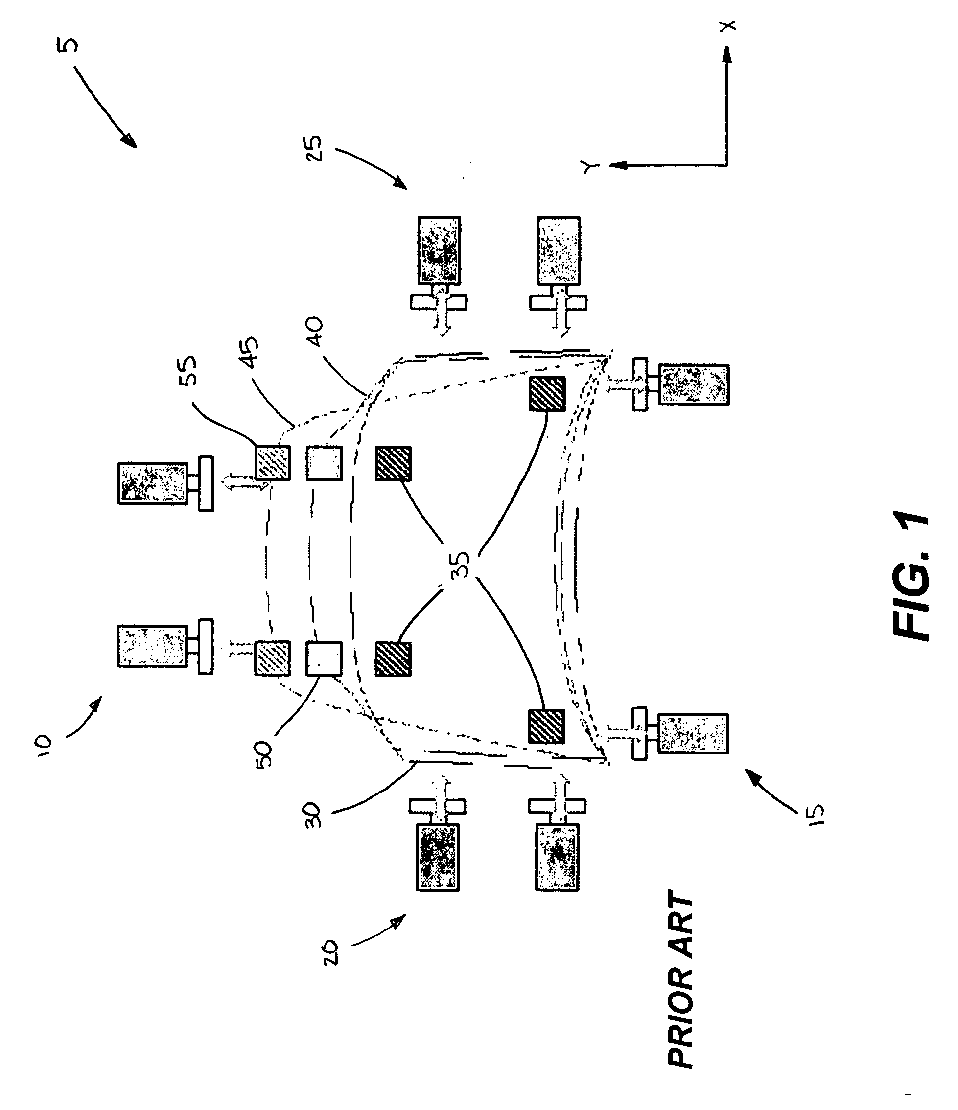
[0027] A known vehicle panel alignment fixture 5 is shown in the top plan view of FIG. 1. Such fixtures may exist to orient / position a variety of panels, but in the particular exemplary embodiment of FIG. 1, the fixture is used to orient / position a vehicle hood skin 30. The fixture may make use of a number of panel supports 35 or even a form fitting part “nest” to receive the hood skin—although such is not shown in detail in FIG. 1 for reasons of clarity.

[0028] As shown, the alignment fixture 5 includes a number of actuator pairs 10, 15, 20, 25 that are used to manipulate the hood skin 30 once it has been placed on the fixture 5. The opposing actuator pairs 10, 15 located at the top and bottom of the vehicle hood skin 30 are used to move the hood skin along the “Y” axis as indicated by the like-labeled arrow. Similarly, opposing actuator pairs 20, 25 located at the left and right sides of the vehicle hood skin 30 are used to move the hood skin along the “X” axis as indicated by th...


PUM

PropertyMeasurementUnit
Angleaaaaaaaaaa
Vacuumaaaaaaaaaa

Abstract

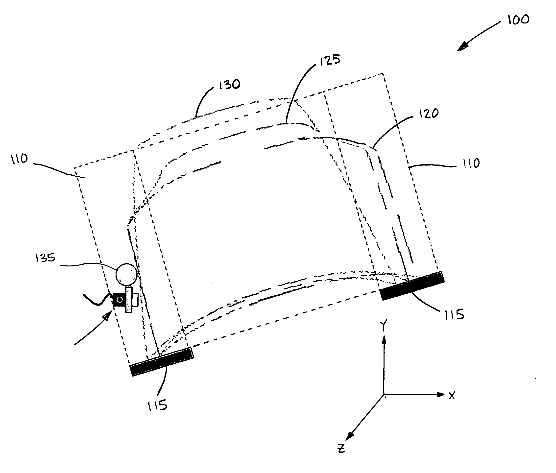
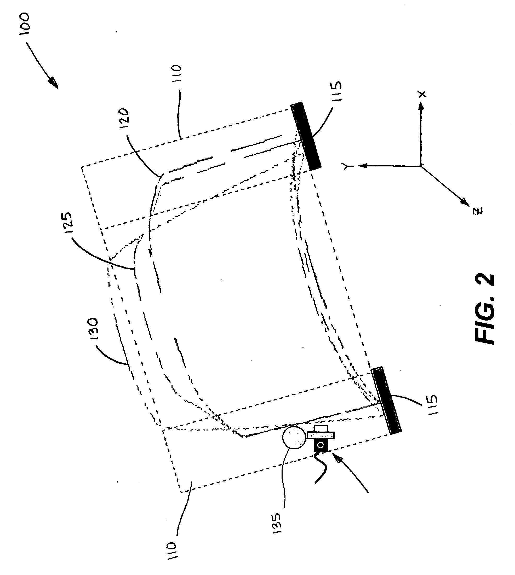
A robotic system and process for automatically orienting / positioning a vehicle panel prior to its installation to a vehicle. The panel is first moved by the robot from a temporary storage position to an alignment fixture that acts to initially define the orientation / position of the panel in two directions. The robot subsequently contacts the panel such that the panel is pushed against a position stop that defines the position of the panel in a third direction. With the panel properly oriented / positioned, the robot removes the panel from the alignment fixture and transfers it to the vehicle for installation. Panels of dissimilar size and / or shape may be installed using the same system and process.

Description

BACKGROUND OF THE INVENTION [0001] The present invention is directed to a robotic process for properly aligning a vehicle panel during a vehicle assembly process. More particularly, the present invention is directed to a robotic process whereby a vehicle panel can be removed from a temporary storage position, such as from a delivery cart, and properly oriented / positioned for robotic pickup and transfer to a vehicle. [0002] Vehicle panels, such as hood skins, are typically delivered to an assembly line via some delivery system. Commonly such panels are delivered on carts that are designed to receive the panels in a delivery and unload section of the assembly plant, and to securely transport the panels to an assembly line where they will be used or installed to a vehicle. These carts may be automated or they may be transported to the desired location by workers using tow motors, tuggers, or various other driven vehicles. [0003] The aforementioned carts are typically designed to ensure...

Claims


Application Information

Patent Timeline
IPC IPC(8): B23Q17/00
CPCB62D65/02Y10T29/49764Y10T29/4978Y10T29/49895
Inventor TSUCHIYA, HIROKICAVINEE, SCOTTCORDELL, ROSSNULL, GREG
Owner HONDA MOTOR CO LTD
Learn More