
Intercepting an uplink signal to assist in timing or positioning calculations

a technology of uplink signal and timing or positioning calculation, applied in the field of uplink signal, can solve the problems of weak reception, inability to be practical in some environments, and requiring the use of the ue to make measurements, and achieve the effect of facilitating trilateration and increasing geometrical diversity

Active Publication Date: 2020-03-12
U-BLOX
View PDF0 Cites 3 Cited by
  • Summary
  • Abstract
  • Description
  • Claims
  • Application Information

AI Technical Summary

Benefits of technology

This patent describes a system that uses interception to improve positioning and timing in wireless networks. By intercepting signals from one device and measuring them from another, the system can create more useful information. This is particularly useful in industrial settings where multiple network operators may be used. The system can also use information from multiple devices to improve accuracy. Overall, this technology provides a cost-effective and flexible solution for positioning in wireless networks.

Problems solved by technology

A disadvantage of downlink-measurement systems is that they require the UE to make the measurements.
This may not be practical in some environments, because the uplink signal is lower power and may be too weak to be received at distant BSs (that is, at BSs other than the BS that is serving the UE).

Method used


Image

  • Intercepting an uplink signal to assist in timing or positioning calculations
  • Intercepting an uplink signal to assist in timing or positioning calculations
  • Intercepting an uplink signal to assist in timing or positioning calculations

Examples


example 1

edules an Uplink Access Request

[0306]FIG. 12 shows a sequence of operations for scheduled measurement of a neighbour donor's access request. In this example, it is assumed that there is a supporting service 190 and a pool of participating neighbours. It might perhaps be the building application use-case, described above with reference to FIG. 7.

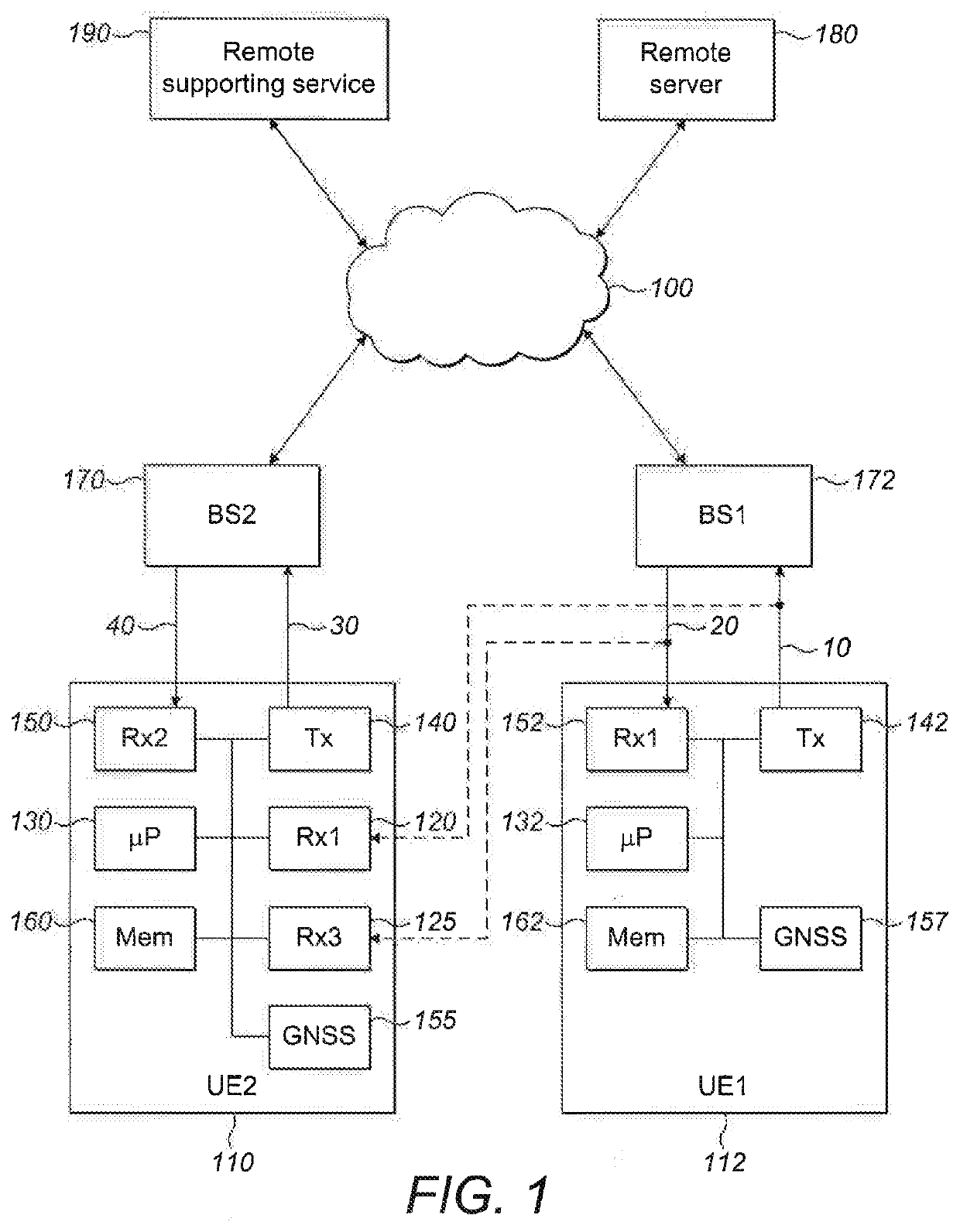
[0307]The listener (UE 110) is in communication with the supporting service 190, via the cellular network and its base station 170 (which might not necessarily be the same base station as the BS 172 serving the donor modem), or by some other means. The listener requests a position, and the supporting service then arranges that the neighbouring donor modems will make transmissions at a schedule of times in the future. A number of donor transmissions may be scheduled, to serve the needs and requests of a number of listeners.

[0308]The uplink signal in this case is an access request (RACH). It is arranged with the donor that this will take place ...

example 2

ink Data Reference Signal Measured

[0311]FIG. 13 shows a sequence of operations for a measurement using the uplink demodulation reference signal. In this example, we use a signal which has better properties for making accurate measurements, the demodulation reference signal (DMRS). This is part of the uplink data signal message, and so is visible when the neighbouring donor modem is in connected mode, transmitting uplink data. The channel allocations for the uplink are determined by the network, and are reported to all users in the Downlink Control Information block. Each connected modem extracts its uplink allocation from this information, with the individual allocations identifiable according to the Cell Radio Network Temporary Identifier (C-RNTI) provided to the modem when it connects to the network for a session.

[0312]In this case, following a request for a position, the supporting service 190 connects to the neighbouring donor (UE 112), establishing a connection by the donor to ...


PUM


Abstract

Methods and apparatus are disclosed for sharing, by a first User Equipment, interception-assistance information relating to an uplink signal transmitted by the first User Equipment. The interception-assistance information may be used to assist a second User Equipment to intercept the uplink signal and measure at least one characteristic of it. Calculation-assistance information may be used to assist in the calculation of a position or in time, based on the measured characteristic.

Description

FIELD OF THE INVENTION[0001]This invention relates to the use of uplink signals for positioning or timing applications. It relates in particular to a User Equipment (UE) transmitting an uplink signal and that uplink signal being intercepted by another UE, for use in positioning or timing calculations.BACKGROUND OF THE INVENTION[0002]Known cellular positioning systems can be divided into two types:[0003]In a downlink measurement system, the device (UE) makes measurements of the time of arrival of the downlink signals from the base stations (BSs), and the measurements are then processed in the device to find the position of the UE, or the measurements are passed up to a positioning engine in the network to find the position of the UE, Systems in which the device does the calculations are known as Mobile-Station-based (MS-based) systems. Those in which the measurements are forwarded to a positioning engine at a remote server are called MS-assisted systems.[0004]A second kind of system ...

Claims


Application Information

Patent Timeline
Patent Type & Authority Applications(United States)
IPC IPC(8): G01S5/02G01S5/00
CPCG01S5/0036G01S5/145G01S5/0236G01S5/0018H04W64/003
Inventor MARSHALL, CHRISTOPHERHERCZOG, PASCALVUJADINOVIC, DUSKO
Owner U-BLOX
Learn More