
Shelf Electrical Supply System

a technology for electrical supply systems and shelves, applied in the direction of electrical discharge lamps, coupling device connections, coupling parts engagement/disengagement, etc., can solve the problems of complicated assembly with shelves, inconvenient installation, complicated structure of shelf electrical supply systems, etc., to facilitate installation between metal guide tracks and track grooves, simplify the overall structure of the system, and increase the area of conductive transmission medium

Active Publication Date: 2020-03-05
SELF ELECTRONICS CO LTD +2
View PDF4 Cites 0 Cited by
  • Summary
  • Abstract
  • Description
  • Claims
  • Application Information

AI Technical Summary

Benefits of technology

The present invention provides a shelf electrical supply system that is simple to assemble, flexible to assemble, and convenient for the user to select an assembly combination according to actual conditions. The system uses a metal guide track as the power transmission medium, which facilitates installation and increases the area of the conductive transmission medium, ensuring stable electricity. The magnet block connects the electrical component to the metal guide track by suction, ensuring stable contact and good electrical effect. The track groove is made of insulating material, allowing the operator to select the connection between the system and the shelf according to the actual material of the shelf, providing a choice space for the customer to use. Personalized design is better.

Problems solved by technology

However, the shelf electrical supply system has a complicated structure, is inconvenient to install, and is also complicated to assemble with the shelf.
If the shelf placement position is not suitable for the exposure of the slotted hole, it will result in difficulty in power taking, and most of the electrical supply heads need to adopt materials that are consistent with the shelf material to facilitate installation.
If the materials are different, it may lead to the failure of fixed assembly between the electrical supply head and the shelf, resulting in no space for the user to choose combination assembly.

Method used


Image

  • Shelf Electrical Supply System
  • Shelf Electrical Supply System
  • Shelf Electrical Supply System

Examples


Embodiment Construction

[0030]Embodiments of the invention are described in detail below, Examples of the embodiments are shown in the appended drawings in which consistently identical or similar labels represent identical or similar elements or elements having the same or similar function. The embodiments described below by reference to the drawings are exemplary and are only used for the interpretation of the invention and cannot be understood to be a limitation of the invention.

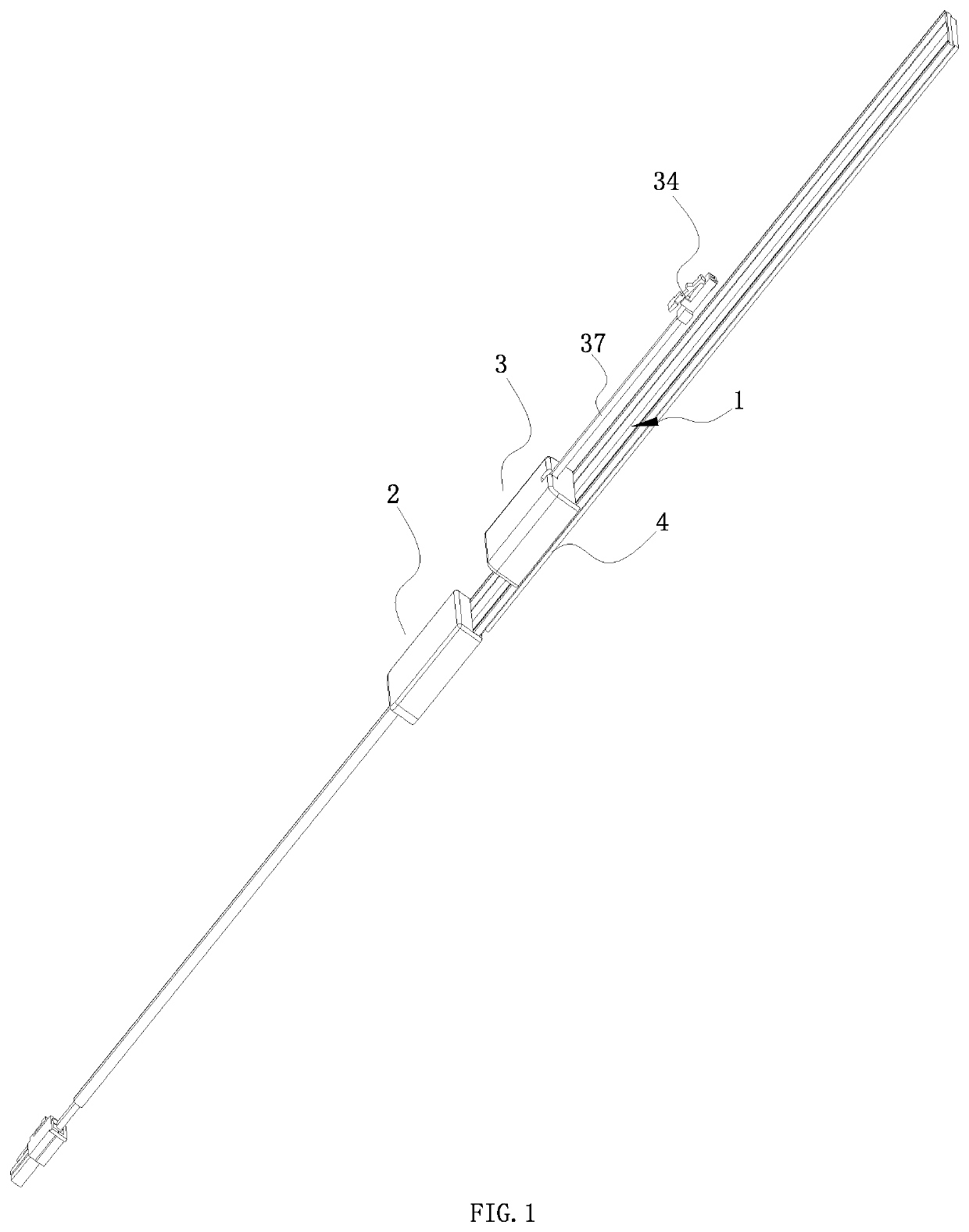
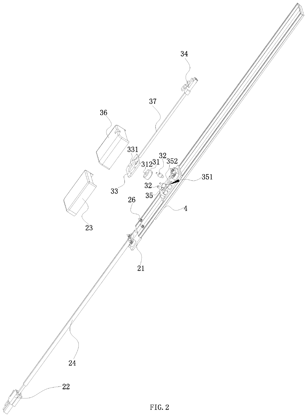
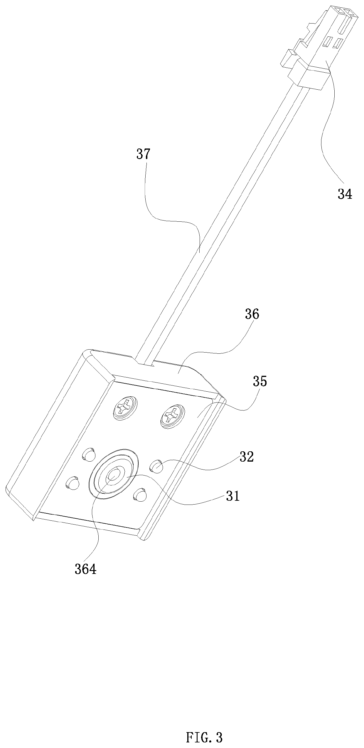
[0031]As shown in FIG. 1-5, it is a preferred embodiment of the shelf electrical supply system of the present application, it should be noted that only one embodiment of the present invention is shown here, which does not mean that the present application is limited to this case. Other lamps and methods that can achieve the functions and effects described in the present application are all within the scope of the present application.

[0032]As shown in FIG. 2 and FIG. 4-5, the shelf electrical supply system comprises a electrical s...


PUM


Abstract

The invention relates to a shelf electrical supply system, comprising electrical supply guide track fixedly connected to a shelf; electrical input part connected to the electrical supply guide track; electrical component disposed on the electrical supply guide track; the electrical supply guide track comprises track groove, metal guide track disposed in the track groove, and the electrical input part is electrically connected to one end of the metal guide track; the electrical component comprises magnet block and conductive contact arranged around the magnet block, and when the electrical component is disposed on the electrical supply guide track, the magnet block is attracted to the metal guide track and the conductive contact is in contact with the metal guide track. The system has simple structure, convenient assembly and better personalized design.

Description

RELATED APPLICATION[0001]This application claims priority to a Chinese Patent Application No. CN 201810991597.9, filed on Aug. 28, 2018.FIELD OF THE TECHNOLOGY[0002]The present invention relates to shelf equipment, with particular emphasis on a shelf electrical supply system.BACKGROUND OF THE INVENTION[0003]Shelves are widely used in shopping malls, supermarkets, logistics storage and other places. In order to be convenient to use, the shelf needs to be equipped with lighting fixtures, and the shelf needs to be space-saving and easy to assemble, which determines its higher requirements for structure and lighting.[0004]In order to meet the above requirements, people have developed shelf electrical supply system, such as the shelf electrical supply disclosed in the Chinese utility model patent CN206318770U “shelf electrical supply head and shelf electrical supply system having same”, the shelf electrical supply head comprises a bottom cover, a top cover set on the bottom cover, positi...

Claims


Application Information

Patent Timeline
IPC IPC(8): H01R31/06H01R33/88H01R13/62H01R13/512H02G3/30
CPCH01R31/06H02G3/30H01R33/88H02G3/305H01R13/512H01R13/6205H01R25/14H01R25/142H01R25/145
Inventor CHEN, DONGDONG, JIANGUO
Owner SELF ELECTRONICS CO LTD
Learn More