High speed switch

Active Publication Date: 2020-03-05
LSIS CO LTD
View PDF0 Cites 3 Cited by
  • Summary
  • Abstract
  • Description
  • Claims
  • Application Information

AI Technical Summary

Benefits of technology

The present patent aims to reveal a high-speed switch that can operate quickly and reliably regardless of environmental factors. The breaker is meant for use in ultra-high voltage lines and is easy to check and maintain. The technical effect of this patent is to provide a reliable and speedy switch for use in high-speed applications.

Problems solved by technology

In addition, the spring mechanism applied to the breaker according to the related art has a problem that it is fundamentally difficult for the breaker using the spring mechanism to achieve an operating speed required in the fault current limiter and the DC breaker.
Thus, when the opening operation speed is increased, a very large impact amount from a moving portion may occur.
In this connection, there is a problem that a size of the permanent magnet actuator must be very large in order to maintain the open state.
Thus, friction is also increased.
When the friction is beyond a certain range, the high-speed operation may not be achieved.
Further, when the breaker operates at a high speed, the breaker may be brought into a re-closed state after the breaking operation due to a large impact amount.

Method used


Image

  • High speed switch
  • High speed switch
  • High speed switch

Examples


first embodiment

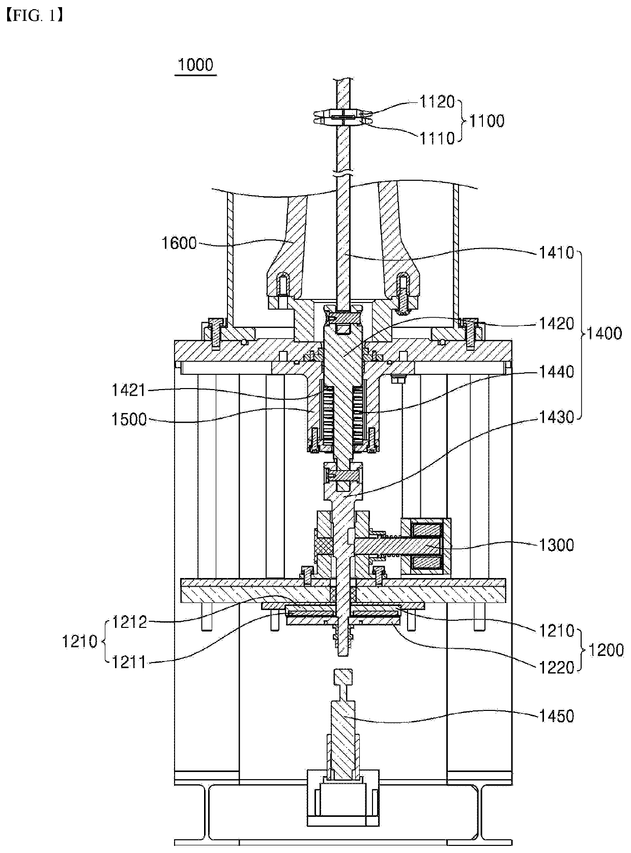
[0037]FIG. 1 is a schematic diagram illustrating a high-speed switch according to the present disclosure. As shown, the high-speed switch 1000 includes current interrupting means 1100, a driving assembly 1200, a state-maintaining assembly 1300, and a guide rod assembly 1400.

[0038]More specifically, the current interrupting means 1100 is connected to the main circuit, and includes a movable electrode 1110 and a fixed electrode 1120 for opening and closing the main circuit. The movable electrode 1110 is connected to a guide rod assembly 1400. As the guide rod assembly 1400 moves, the movable electrode 1110 comes into contact with the fixed electrode 1120 to bring a closed state or is separated from the fixed electrode 1120 to bring an open state.

[0039]The current interrupting means 1100 is contained in a gas tank 1600 in which gas is sealed.

[0040]Further, the driving assembly 1200 is configured for moving the movable electrode 1110 to provide a driving force to bring an open state. Fo...

second embodiment

[0074]FIG. 5 is a schematic diagram of a high-speed switch according to the present disclosure.

[0075]As shown, the high-speed switch 2000 differs from the high-speed switch 1000 shown in FIG. 1 only in terms of a configuration of the state-maintaining assembly.

[0076]The high-speed switch 2000 includes current interrupting means 2100, a driving assembly 2200, a state-maintaining assembly 2300, and a guide rod assembly 2400.

[0077]Further, the current interrupting means 2100 and the driving assembly 2200 are the same as the current interrupting means 1100 and the driving assembly 1200 of the high-speed switch 1000 shown in FIG. 1, respectively. Descriptions of configurations thereof will be omitted. Further, the guide rod assembly 2400 is the same as the guide rod assembly 1400 shown in FIG. 1. Only the latch groove of the latch rod is different between the high-speed switches 1000 and 2000.

[0078]More specifically, the state-maintaining assembly 2300 includes a first fixing unit 2300a ...

third embodiment

[0087]FIG. 6 is a schematic diagram illustrating a high-speed switch according to the present disclosure.

[0088]As shown in the figure, the high-speed switch 3000 is different from the high-speed switch 1000 according to the first embodiment shown in FIG. 1 only in terms of a shape of an end of the latch pin and a shape of the latch groove corresponding to the end of the latch pin.

[0089]More specifically, one end of the latch pin 3310 has a first end 3311 and a second end 3312. The first end 3311 is a distal end extending from the second end. The first end 3311 is smaller than the second end 3312. The first end 3311 is formed in a stepped manner from the second end 3312.

[0090]A latch groove 3431 of the latch rod 3430 includes a first groove 3431a corresponding to the first end 3311 and a second groove 3431b corresponding to the second end 3312.

[0091]Further, when the latch pin 3310 is inserted into the latch groove 3431, the first end 3321 is inserted into the first groove 3431a, whi...


PUM


Abstract

A high speed switch comprises an interrupter unit connected to a main circuit and including a movable electrode and a driving electrode for opening or closing the main circuit; a driving unit including a repulsion coil for providing a driving force for moving the movable electrode of the interrupter unit, and a repulsion plate disposed opposite to the repulsion coil; a guide rod part connecting the movable electrode of the interrupter unit to the repulsion plate, having a latch groove formed therein, and reciprocating vertically according to movements of the repulsion plate; and a state-holding unit for regulating the movement of the guide rod part, wherein the state-holding unit comprises: a latch; a latch elastic member; and a latch coil.

Description

TECHNICAL FIELD[0001]The present disclosure relates to a high-speed switch, and, more specifically, to a high-speed switch having a sealing structure capable of gas insulation, and having increased operating speed and improved reliability against environmental variables by maintaining an open state using a mechanical state-maintaining assembly.BACKGROUND ART[0002]In general, a high-speed switch is a power device that can interrupt fault currents such as short-circuit currents at a high speed or to bring a circuit into a closed state by switching into an open or closed state at a high-speed.[0003]The high-speed switch operates at high-speed from milliseconds to tens of milliseconds, thereby to minimize influence of arc generated when the circuit is opened and closed and to quickly break the fault current, thereby reducing the damage of the power device such as a power distribution board.[0004]More specifically, in a conventional power system, a fault current limiter is to operate at ...

Claims


Application Information

Patent Timeline
IPC IPC(8): H01H33/50H01H33/56H01H33/38H01H33/42
CPCH01H33/50H01H33/565H01H33/38H01H33/42H01H33/28H01H3/60H01H33/285H01H1/50
Inventor PARK, HAE-YONGSIM, JUNG-WOOKLEE, GYEONG-HO
Owner LSIS CO LTD
Why Eureka
Try Eureka