
Storage system and management method thereof

a storage system and management method technology, applied in the field of storage systems, can solve the problems of difficult to set the trigger threshold, difficult to distinguish between a peak period of heavy operations and an off-peak period, and limited utilization of background operation procedures, so as to facilitate the storage system, improve the efficiency and flexibility of the storage system, and influence the performance of the storage system

Inactive Publication Date: 2020-02-13
APACER
View PDF9 Cites 0 Cited by
  • Summary
  • Abstract
  • Description
  • Claims
  • Application Information

AI Technical Summary

Benefits of technology

The present patent is about a storage system that uses a timestamp to manage its operations. The system calculates the number of operations performed in different time intervals and identifies periods of peak activity and low activity to improve its performance. By setting a triggering time for background operations during off-peak periods, the storage system can avoid interfering with its main functions. The use of a timestamp also makes it easier to visualize and analyze statistic data, providing useful information to users and enterprise customers.

Problems solved by technology

However, in the storage system kept in operation for a long term, for example a storage system in a server, the idle time is short, so that it is difficult to set the trigger threshold for the background operation procedure, and it is difficult to distinguish between a peak period of heavy operations and an off-peak period.
Consequently, the utilization of the background operation procedure is limited, and the flexibility of its function is also limited.

Method used

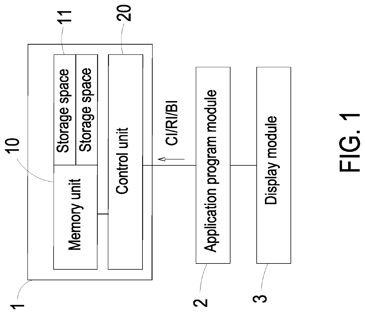

Image

  • Storage system and management method thereof
  • Storage system and management method thereof
  • Storage system and management method thereof

Examples


first embodiment

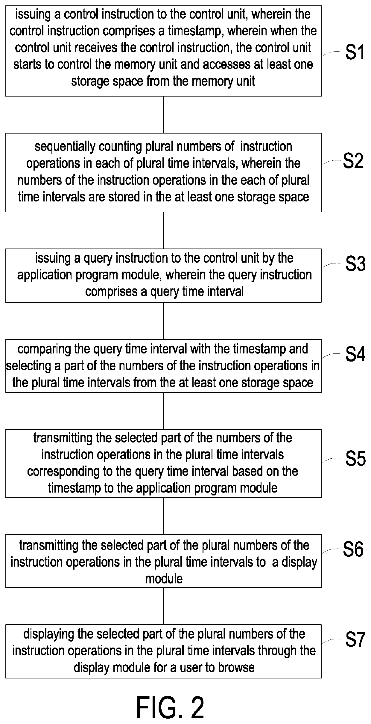
[0040]FIG. 1 is a functional block illustrating a storage system and an application program module applied thereto according to an embodiment of the present disclosure. FIG. 2 is a flow chart illustrating a management method of the storage system according the present disclosure. The storage system 1 includes a memory unit 10 and a control unit 20. The memory unit 10 includes at least one storage space 11. The control unit 20 is connected with the memory unit 10 and configured to control the memory unit 10. In the embodiment, the control unit 20 of the storage system 1 is further connected with an application program module 2. The application program module 2 is configured to issue at least one control instruction CI to the control unit 20. Firstly, at the step S1, when the control unit 20 of the storage system 1 receives the control instruction CI, the control unit 20 starts to control the memory unit 10 and accesses at least one storage space 11 from the memory unit 10. The contro...

second embodiment

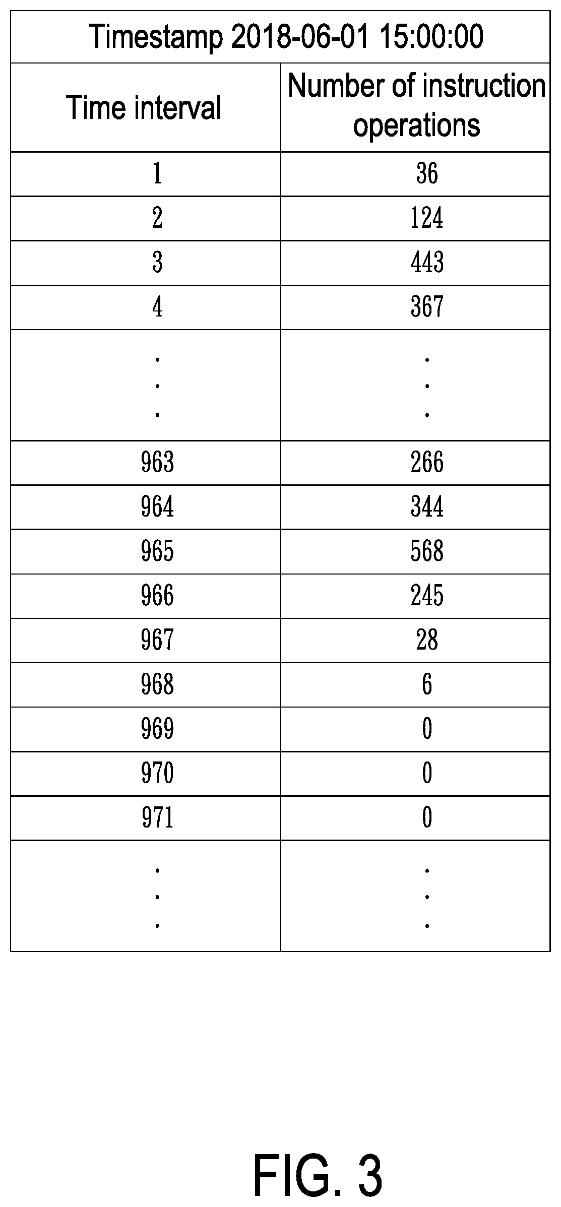
[0046]FIG. 10 is a flow chart illustrating a management method of the storage system according the present disclosure. As shown in FIGS. 1 and 10, the steps S1′ and S2′ are similar to the steps S1 and S2 of FIG. 2, and not redundantly described herein. In the embodiment, at the step S1′ and S2′, the storage system 1 stores the plural numbers of the instruction operations in the plural time intervals in the storage space 11 based on the received timestamp. At the step S3′, a background operation instruction BI, such as data backup instruction, is further issued to the control unit 20 of the storage system 1 by the application program module 2. Then, at the step S4′, when the control unit 20 receives the background operation instruction BI, at least one off-peak period is selected from the plural time intervals through the control unit 20 by comparing each of the plural numbers of the instruction operations in each of the plural time intervals. In the embodiment, the number of the ins...

third embodiment

[0049]FIG. 13 is a flow chart illustrating a management method of the storage system according the present disclosure. As shown in FIGS. 1 and 13, the steps S1″ and S2″ are similar to the steps S1 and S2 of FIG. 2, and not redundantly described herein. In the embodiment, at the step S1″ and S2″, the storage system 1 stores the plural numbers of the instruction operations in the plural time intervals, which are stored in the storage space 11, based on the received timestamp. At the step S3″, at least one off-peak period and at least one peak period are selected from the plural time intervals through the control unit 1 by comparing the plural numbers of the instruction operations in each of the plural time intervals, respectively. The number of the instruction operations in the selected time interval corresponding to the at least one peak period is more than the number of the instruction operations in the selected time interval corresponding to the at least one off-peak period. While ...


PUM


Abstract

A storage system capable of executing a managing operation based on timestamp and a management method are disclosed. The storage system includes a control unit and a memory unit connected to the control unit. The management method includes steps of: (a) issuing a control instruction comprising a timestamp to the control unit, wherein when the control unit receives the control instruction, the control unit starts to control the memory unit and accesses at least one storage space from the memory unit; and (b) sequentially counting plural numbers of instruction operations in plural time intervals, wherein the plural numbers of the instruction operations in each of the plural time intervals are stored in the at least one storage space. Since the peak period and the off-peak period of the storage system can be counted based on the timestamp, it facilitates the storage system to set a triggering time to execute a background operation.

Description

FIELD OF THE INVENTION[0001]The present disclosure relates to a storage system, and more particularly to a storage system capable of executing a managing operation based on a timestamp and a management method thereof.BACKGROUND OF THE INVENTION[0002]In order to manage storage space effectively, some background operations such as garbage collection (GC) and smart background data collection are performed in a conventional storage system, for example, while the storage system of a disk is idle for a period of time.[0003]As to the triggering time of executing the aforementioned background operation procedure, since the conventional storage system performs a time calculation by a time clock after the conventional storage system is powered up, the time clock can record the time merely after the storage system is powered up. When the conventional storage system needs to trigger the aforementioned background operation procedure, it is necessary to determine a triggering time with a trigger ...

Claims


Application Information

Patent Timeline
Patent Type & Authority Applications(United States)
IPC IPC(8): G06F3/06G06F9/38G06F9/50G06F11/34G06F17/30
CPCG06F9/505G06F9/3836G06F11/3423G06F16/9038G06F16/907G06F3/0671G06F3/0604G06F3/0631G06F3/061G06F3/0659G06F11/3034G06F11/3055G06F2201/81G06F2201/835G06F2201/88
Inventor LIU, PO-JUNG
Owner APACER
Learn More