
Speaker box

a speaker box and box body technology, applied in the field of electroacoustic transducers, can solve the problems of monotonous structure, poor sound quality, and poor sound quality of the speaker box, and achieve the effects of reducing the cost of production, harsh sounds, and reducing the acoustic performance of the speaker box

Active Publication Date: 2020-02-06
AAC TECH PTE LTD
View PDF2 Cites 4 Cited by
  • Summary
  • Abstract
  • Description
  • Claims
  • Application Information

AI Technical Summary

Benefits of technology

The present patent discusses a speaker box design that includes an auxiliary acoustic cavity, which is enclosed with the shell, surrounding wall, and support wall and cover plate. This auxiliary cavity acts as a resonant cavity, which increases the volume of the front cavity and improves the high frequency acoustic performance. This design helps to enhance the overall quality of the speaker box.

Problems solved by technology

However, in the speaker box of the related art, the space of the front cavity is limited to a region rightly opposite to a dome and a region of the sound guiding channel, and the structure is monotonous and may not be optimized.
Therefore, high-frequency acoustic performance of the speaker box is subject to restrictions, and over-high high-frequency responses may cause harsh sounds, sharp dentilabial sounds and the like poor sound effects.

Method used


Image

  • Speaker box
  • Speaker box
  • Speaker box

Examples


Embodiment Construction

[0010]The present disclosure will hereinafter be described in detail with reference to several exemplary embodiments. To make the technical problems to be solved, technical solutions and beneficial effects of the present disclosure more apparent, the present disclosure is described in further detail together with the figure and the embodiments. It should be understood the specific embodiments described hereby is only to explain the disclosure, not intended to limit the disclosure.

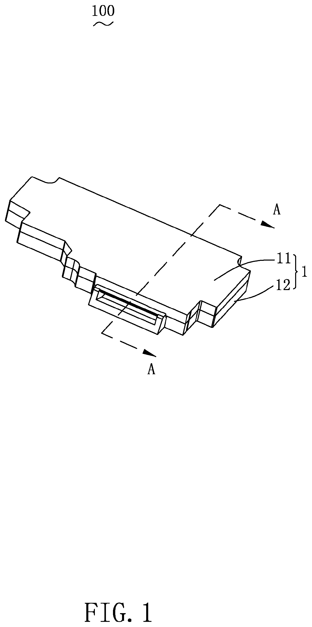
[0011]Please also refer to FIG. 1 to FIG. 3, wherein FIG. 1 is a three-dimensional structure diagram of the speaker box of the present disclosure, FIG. 2 is a partial three-dimensional perspective diagram of the speaker box exploded view, and FIG. 3 is a cross-sectional diagram along the A-A line showing in FIG. 1. The present disclosure provides a speaker box 100. The speaker box 100 comprises a shell 1 having receiving space 10, a speaker 2, a support wall 3, a sound guiding channel 4, a surrounding wall ...


PUM


Abstract

The present disclosure provides a speaker box which comprises a shell, a support wall, a sound guiding channel, a surrounding wall and a cover plate. The speaker is fixed to support the support wall. The diaphragm of the speaker partitions the receiving space into a front sound cavity and a rear cavity, the sound guiding channel communicates the front sound cavity with the outside and forms a front cavity together with the front sound cavity, the shell, the surrounding wall, the support wall and the cover plate are jointly enclosed as an auxiliary acoustic cavity. The support wall is provided with at least two through-holes intervals, and the auxiliary acoustic cavity is communicated with the front cavity through the through-hole to form a resonant cavity structure of the front cavity. Compared with the related art, the high frequency acoustic performance of the speaker box of the present disclosure is excellent.

Description

FIELD OF THE DISCLOSURE[0001]The present disclosure relates to electro-acoustic transducers, and more particularly to a speaker box used in a portable electronic device.DESCRIPTION OF RELATED ART[0002]With the arrival of the mobile internet era, the number of smart mobile devices is being increasing. However, in all these mobile devices, mobile phones are the most common and portable mobile terminal deices. At present, mobile phones are powerful functionality, and one of the powerful functions is the high-quality music function. Therefore, speaker boxes for playing music are widely applied to conventional smart mobile devices.[0003]A speaker box of the related art comprises a shell having a receiving space, a speaker accommodated in the shell and a sound guiding channel defined in the receiving space. The speaker comprises a diaphragm for producing sound via vibrating, the diaphragm partitions the receiving space into a front sound cavity and a rear cavity. The sound guiding channel...

Claims


Application Information

Patent Timeline
IPC IPC(8): H04R1/02
CPCH04R1/023H04R2499/11H04R1/025H04R1/345
Inventor WU, JUNSHEN, KAIHUASUN, WANG
Owner AAC TECH PTE LTD
Learn More