Cutting disk

Inactive Publication Date: 2020-02-06
ALBERT KNEBEL HLDG
View PDF6 Cites 0 Cited by
  • Summary
  • Abstract
  • Description
  • Claims
  • Application Information

AI Technical Summary

Benefits of technology

The invention is about a cutting disk for use with fiber-reinforced composite materials that are difficult to machine. The cutting disk has teeth that are arranged with ideal angles for circumferential and flank machining, which results in a high-quality surface quality. The teeth are arranged efficiently, using a decoupling method, to prevent delamination and fiber protrusion. The cutting surface is further improved by arranging a flank tooth with the same cutting angle as the main cutting edge. The cutting disk can also have a ring-shaped notch or cutout to prevent contact with the workpiece and reduce temperatures during the cutting process. The cutting disk can be produced from a solid material or separate component parts. The teeth can be made from cemented carbide, diamond, or other suitable materials that have a long service life. The teeth can be soldered, glued, or fastened to the base body using positive engagement or bonding. This innovation provides an effective solution for machining difficult-to-machine materials.

Problems solved by technology

Therefore, the orientation of the main cutting edge and secondary cutting edge cannot simultaneously be optimally adjusted to the respective machining task.

Method used


Image

  • Cutting disk
  • Cutting disk
  • Cutting disk

Examples


Embodiment Construction

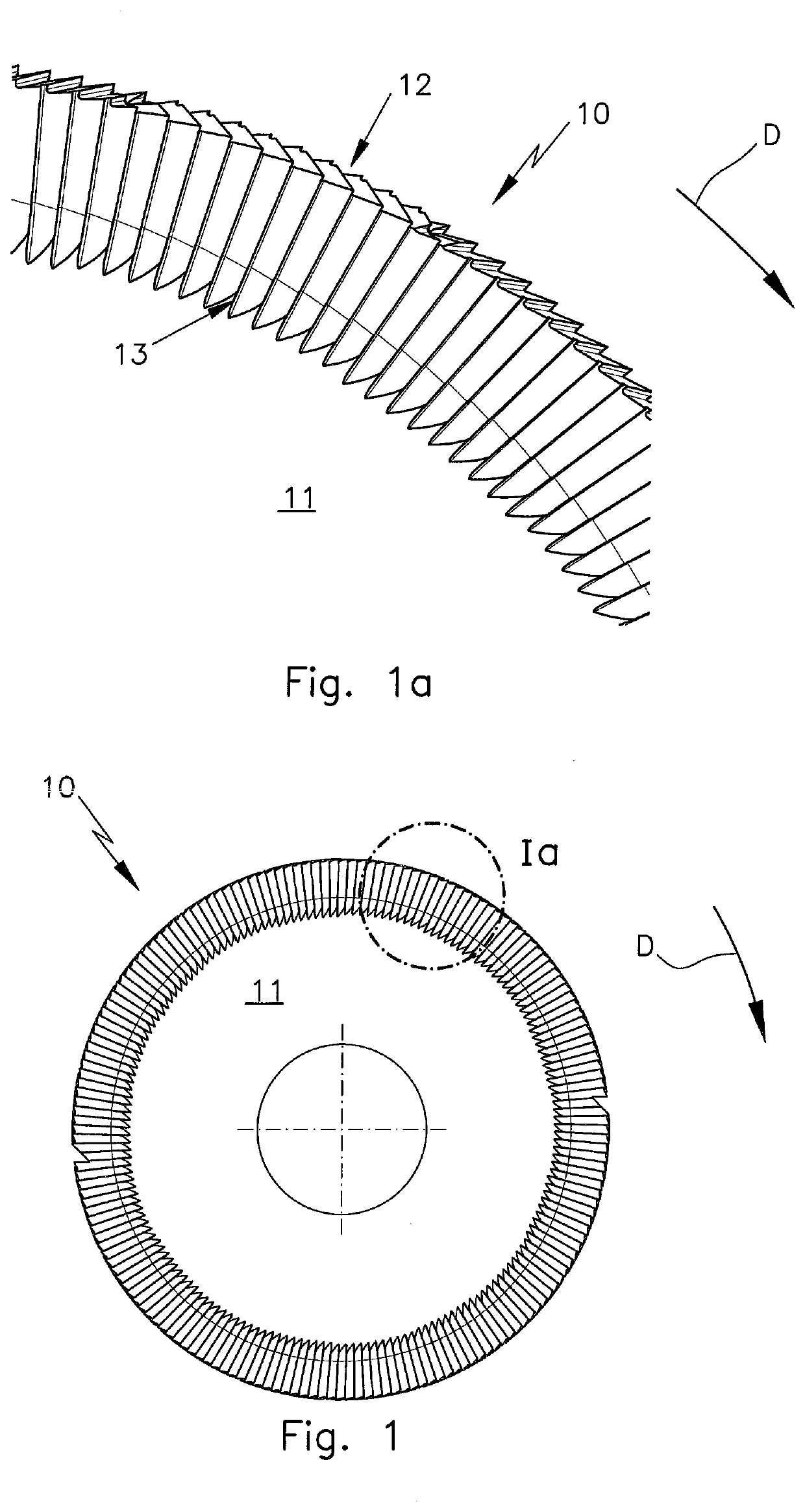
[0025]The cutting disk 10 in FIGS. 1, 1a has a base body 11, a gapless circumferential toothing 12 and a gapless flank toothing 13. The flank toothing 13 is located in the outer radial area of the base body 11 and directly adjoins the circumferential toothing 12. The rotational direction of the cutting disk 10 and of the cutting disks in the other figures is indicated in each instance by an arrow D.

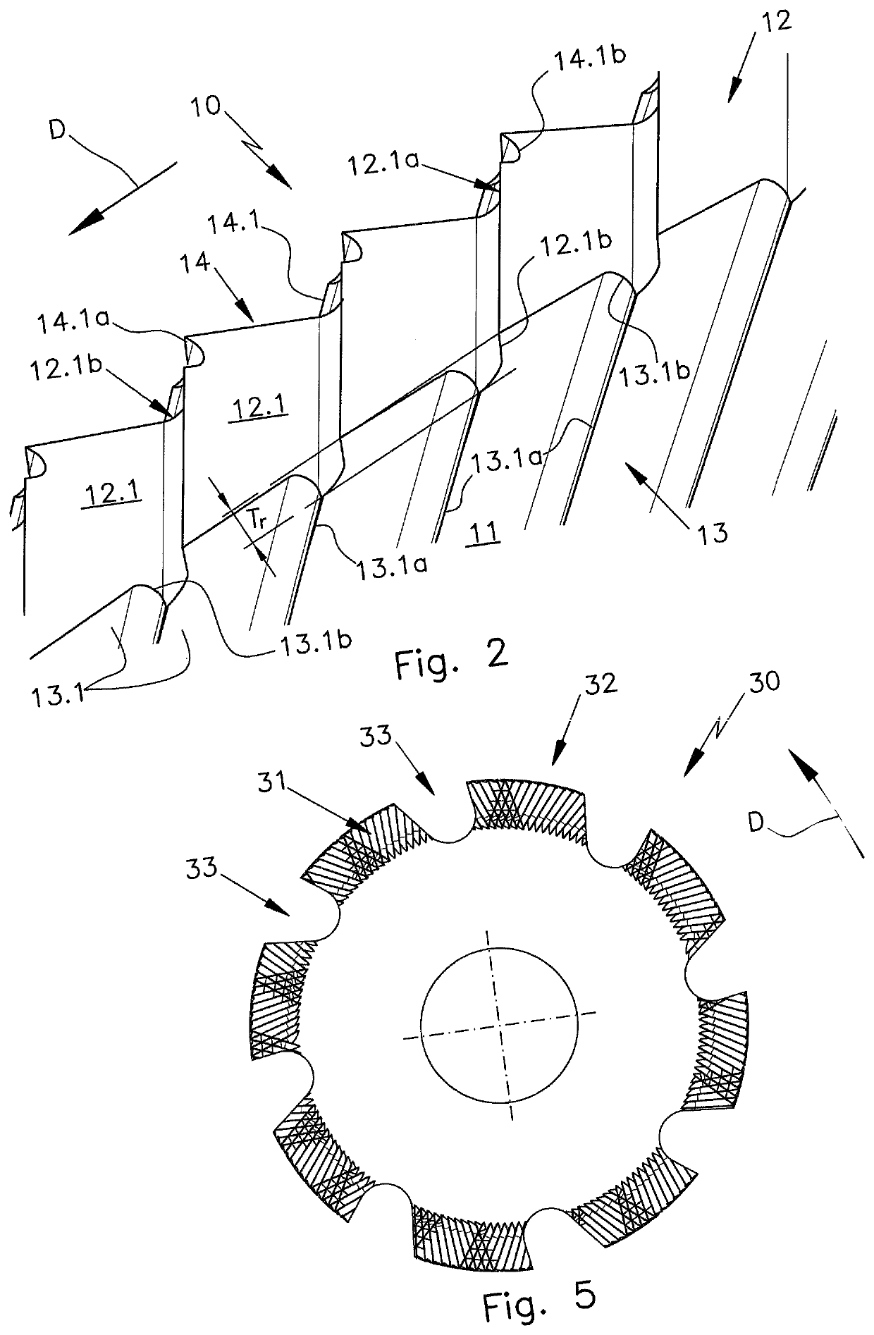
[0026]The detail view of the toothing of the cutting disk 10 in FIG. 2 looking at the opposite lateral surface shows that the base body 11 is also provided with a flank toothing 14 on its opposite lateral surface. The detail view in FIG. 2 further shows that the circumferential toothing 12 is formed by a plurality of circumferential teeth 12.1, and every circumferential tooth 12.1 has a main cutting edge 12.1a and two secondary cutting edges 12.1b. The flank toothing 13, on the other hand, is formed by a plurality of identical flank teeth 13.1 having a main cutting edge 13.1a and a second...


PUM

PropertyMeasurementUnit
Angleaaaaaaaaaa
Areaaaaaaaaaaa
Circumferenceaaaaaaaaaa

Abstract

A cutting disk for workpieces, particularly workpieces of fiber-reinforced composite materials, has a base body which is provided at least in some areas with a circumferential toothing and with a flank toothing arranged on at least some areas and on at least one lateral surface. At least with the majority of circumferential teeth, the main cutting edges do not directly encounter the main cutting edges of the adjacent flank teeth, and the main cutting edges accordingly do not define a common rake face.

Description

CROSS-REFERENCE TO RELATED APPLICATIONS[0001]This application claims priority under 35 USC 119 of German Application No. 10 2018 118 959.1, filed on Aug. 3, 2018, the disclosure of which is herein incorporated by reference.BACKGROUND OF THE INVENTION[0002]The invention is directed to a cutting disk for cutting and / or making grooves in workpieces, particularly workpieces of fiber-reinforced composite materials, with a disk-shaped base body which is provided at least in some areas with a circumferential toothing and with a flank toothing which is arranged at least in some areas at least on one lateral surface.[0003]At the present time, various tools are used to machine composite structural component parts of fiber-reinforced composite materials. End mills of cemented carbide or cemented carbide saws or saws with soldered polycrystalline diamonds with conventional tooth geometries are used. It is also possible to use diamond-coated cutting disks with an indeterminate cutting geometry. ...

Claims


Application Information

Patent Timeline
IPC IPC(8): B23D3/02
CPCB23D3/02B26D1/0006B26D2001/0053B23C5/08B23C2210/326B23C2226/27B23D61/025
Inventor WOERMANN, PHILIPPHERMBUSCHE, GUENTER
Owner ALBERT KNEBEL HLDG
Why Eureka
Try Eureka