
Analog-to-digital converter

a converter and analog-to-digital technology, applied in the field of analog-to-digital converters, can solve the problem of high instability of adc b>100/b>, and achieve the effect of improving stability and reducing isi

Active Publication Date: 2020-01-23
REALTEK SEMICON CORP
View PDF3 Cites 0 Cited by
  • Summary
  • Abstract
  • Description
  • Claims
  • Application Information

AI Technical Summary

Benefits of technology

The present invention provides an analog-to-digital converter (ADC) that can reduce inter-symbol interference (ISI) and avoid circuit instability caused by mismatching common-mode voltages. This results in improved performance compared to conventional technology.

Problems solved by technology

Moreover, when the common-mode voltage of the reference voltage Vth is different from the common-mode voltage of the input voltage Vin, the ADC 100 is highly unstable.

Method used


Image

  • Analog-to-digital converter
  • Analog-to-digital converter
  • Analog-to-digital converter

Examples


Embodiment Construction

[0017]The following description is written by referring to terms of this technical field. If any term is defined in this specification, such term should be explained accordingly. In addition, the connection between objects or events in the below-described embodiments can be direct or indirect provided that these embodiments are practicable under such connection. Said “indirect” means that an intermediate object or a physical space exists between the objects, or an intermediate event or a time interval exists between the events.

[0018]The disclosure herein includes analog-to-digital converters (ADCs). On account of that some or all elements of the ADC could be known, the detail of such elements is omitted provided that such detail has little to do with the features of this disclosure and this omission nowhere dissatisfies the specification and enablement requirements. A person having ordinary skill in the art can choose components equivalent to those described in this specification to...


PUM


Abstract

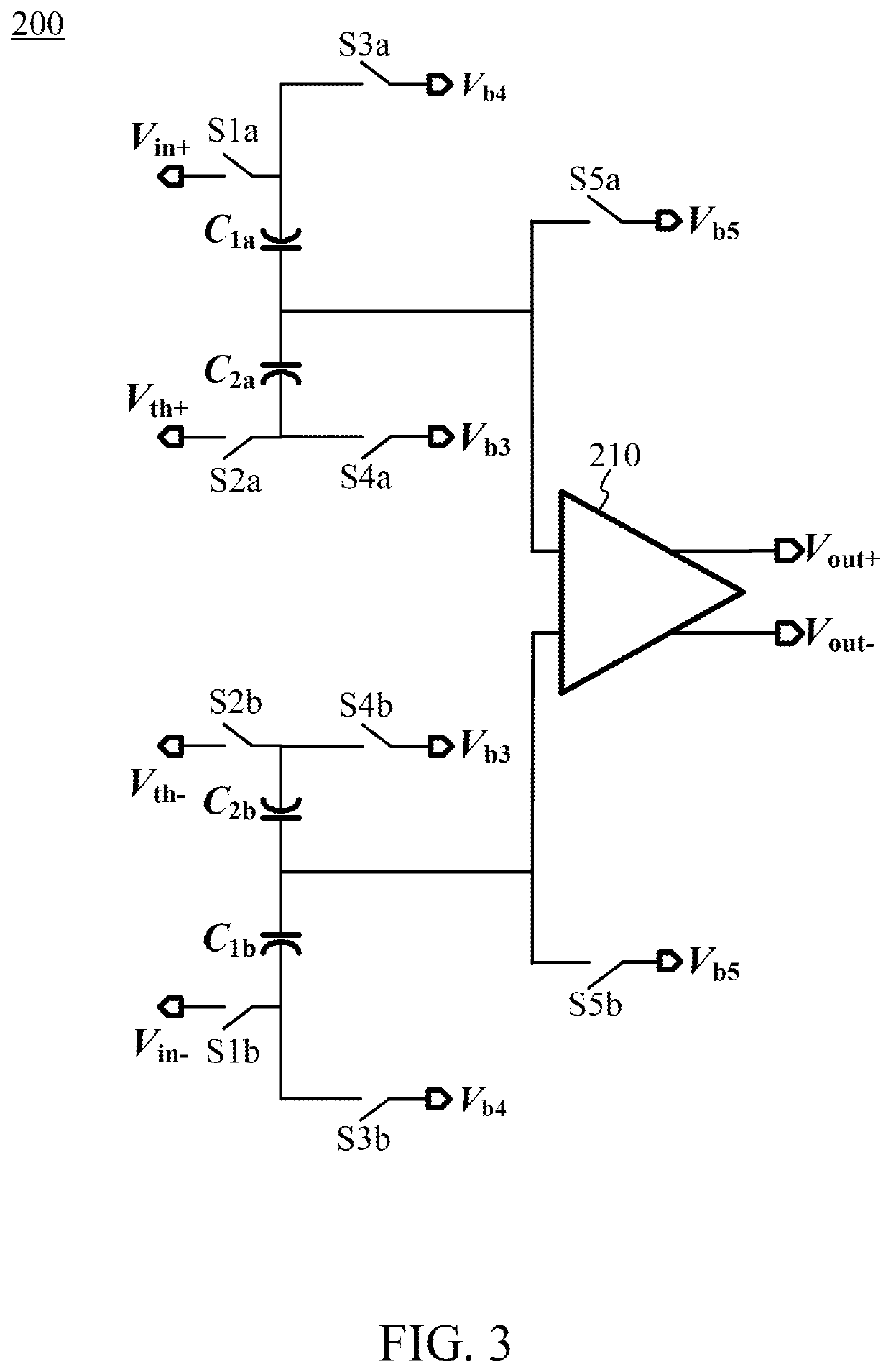
The present invention discloses an analog-to-digital converter (ADC) including an analog circuit, a first switch, a second switch, a first capacitor, and a second capacitor. The analog circuit has a first input terminal and a second input terminal and is configured to amplify and / or compare signals on the first input terminal and the second input terminal. One end of the first capacitor is coupled to the first input terminal, and the other end receives an input voltage via the first switch. One end of the second capacitor is coupled to the first input terminal, and the other end receives a reference voltage via the second switch.

Description

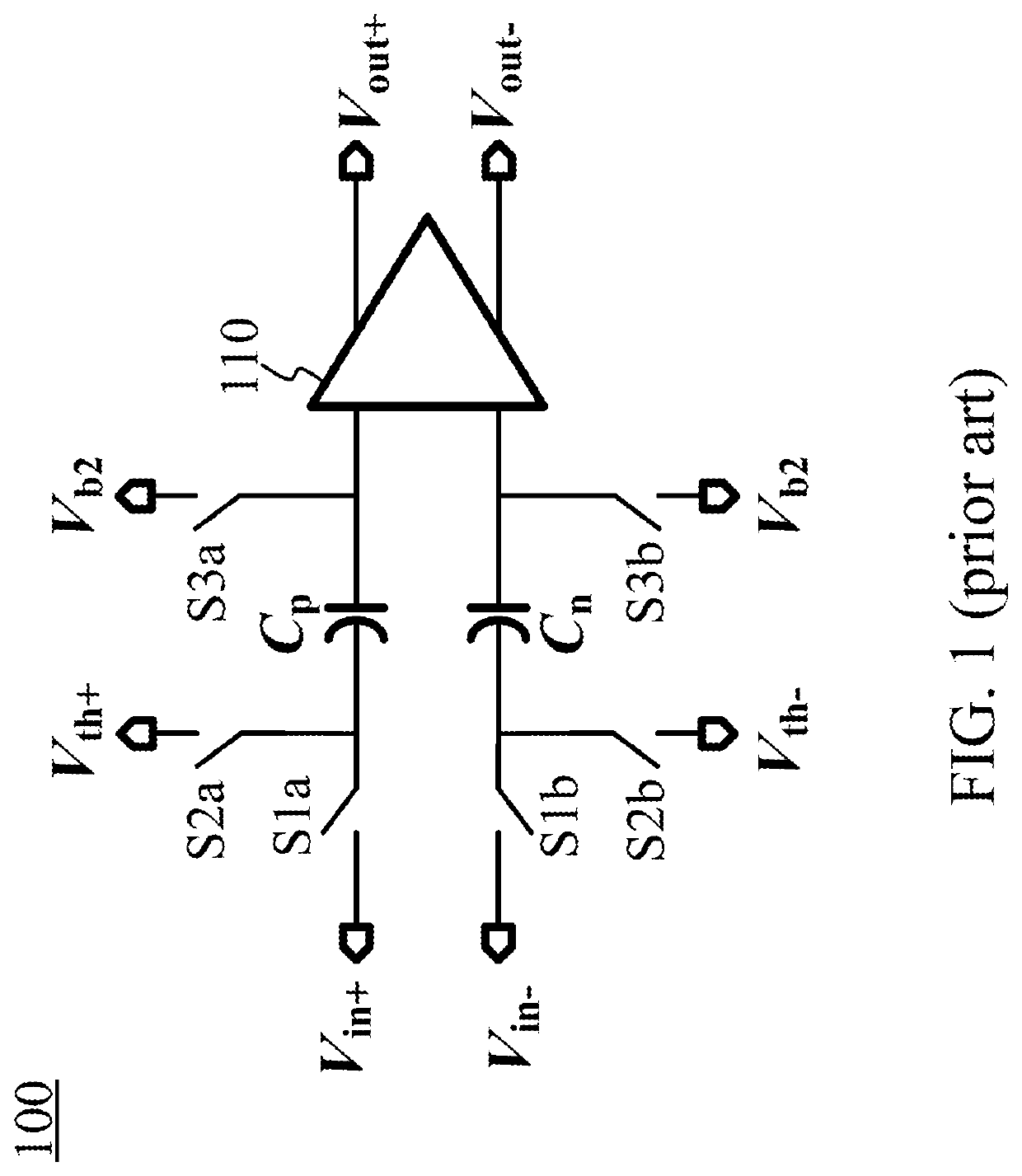
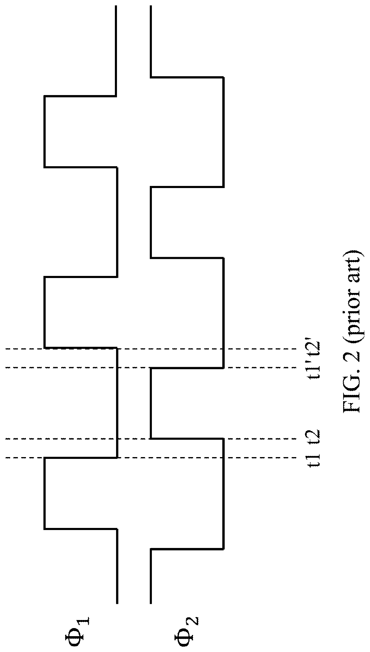
BACKGROUND OF THE INVENTION1. Field of the Invention[0001]The present invention relates to analog-to-digital converters (ADCs).2. Description of Related Art[0002]FIG. 1 is a circuit diagram of a conventional ADC. The ADC 100 includes a comparator 110, a capacitor Cp, a capacitor Cn, and switches S1a, S2a, S3a, S1b, S2b, and S3b. The ADC 100 operates alternately between the first phase and the second phase according to two non-overlapping clocks θ1 and θ2 (as shown in FIG. 2). If the circuit acts or becomes active (e.g., turning on switches) at high levels of the clock, then the first phase would be the high level periods of one of the two non-overlapping clocks, the second phase would be the high level periods of the other clock, and “non-overlapping” means that the two clocks are not high at the same time. The clocks θ1 and θ2 have non-overlapping intervals—between time points t1 and t2 and between time points t1′ and t2′. Even if the falling edge of the clock θ1 is substantially a...

Claims


Application Information

Patent Timeline
Patent Type & Authority Applications(United States)
IPC IPC(8): H03M1/44H03K5/24
CPCH03K5/24H03M1/442H03M1/1245H03M1/468
Inventor WU, YING-CHENGHUANG, SHIH-HSIUNG
Owner REALTEK SEMICON CORP
Learn More