
Amplification apparatus and amplification method

a transmission apparatus and efficiency technology, applied in the direction of amplifiers, electrical apparatus, amplifier modifications to reduce noise influence, etc., can solve the problems of narrow dynamic range of chireix combiner, and loss of 3 db, so as to reduce the amount of calculation processing and small circuit configuration

Active Publication Date: 2020-01-23
NEC CORP
View PDF0 Cites 1 Cited by
  • Summary
  • Abstract
  • Description
  • Claims
  • Application Information

AI Technical Summary

Benefits of technology

The present patent describes how to use a small circuit to compensate for non-linearity and inter-branch amplitude imbalance in an amplification apparatus. This helps to reduce the amount of calculation processing needed and makes the circuit more efficient.

Problems solved by technology

However, the LINC type amplification apparatus uses, for example, a hybrid or 3 dB coupler which causes a loss of 3 dB at the time of combining signals as a combining unit that combines output signals of the two amplifiers.
This leads to a problem that a dynamic range of an amplitude (output power) of an outphasing combined signal, which is an output signal of the Chireix combiner, becomes narrow.
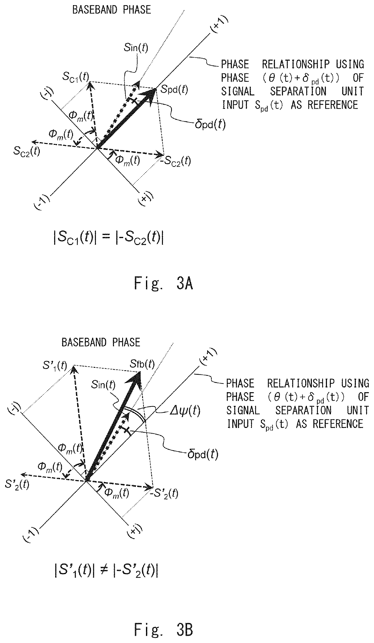
This is because of an amplitude imbalance of output signals of the respective amplifiers caused by the above asymmetric input impedance, which reduces an amount of cancellation of the amplitude of the outphasing combined signal when a phase difference of input signals to the Chireix combiner from the two amplifiers is increased to control the amplitude of the outphasing combined signal to be small in an outphasing control operation.
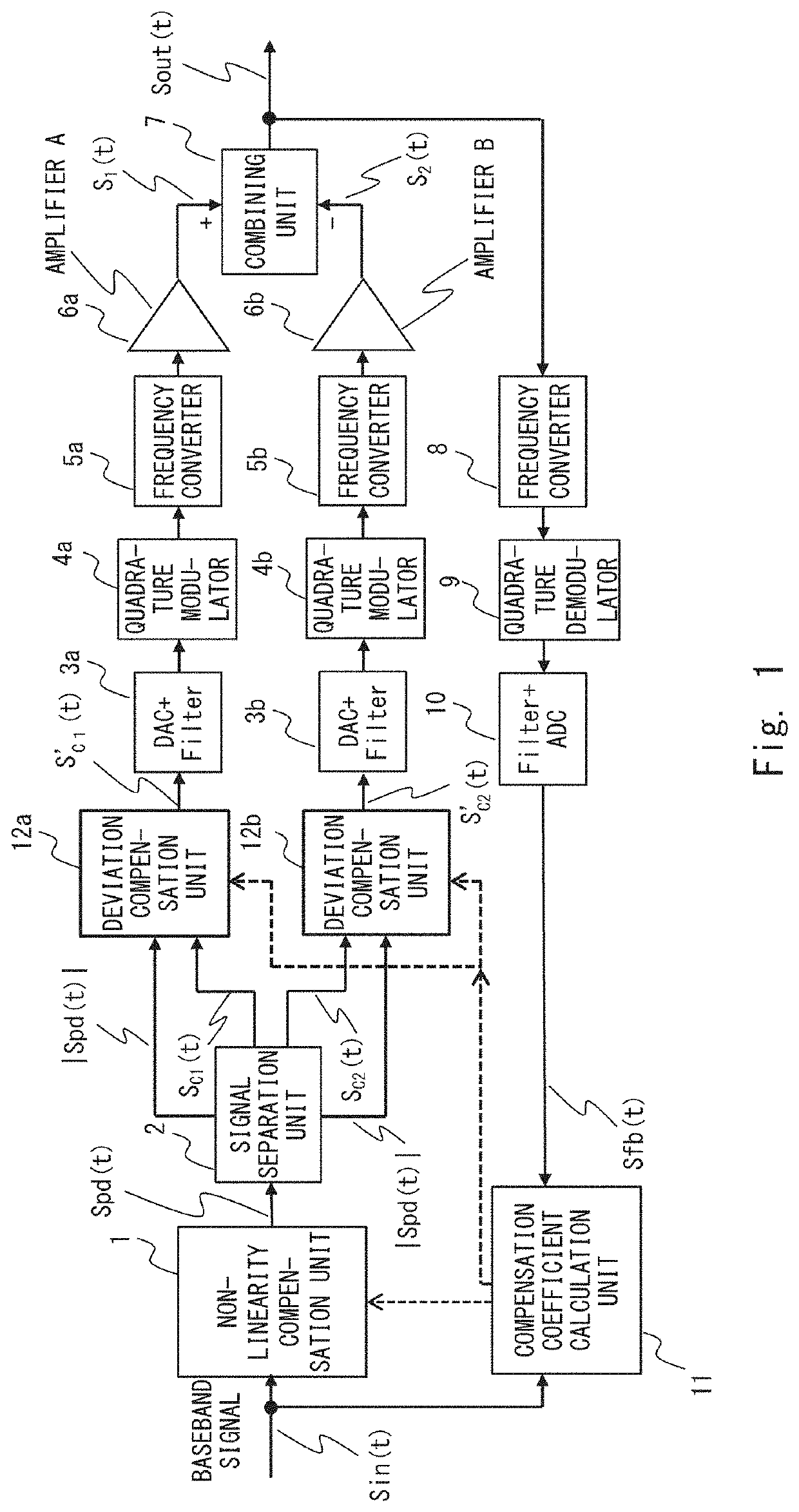
Thus, there is a problem that non-linearity is generated in the outphasing combined signal Sout(t), which is the output signal of the combining unit 7, even when a constant amplitude amplifier such as a saturation amplifier is used as the amplifiers 6a and 6b.
This leads to another problem that a dynamic range of the amplitude (output power) of the outphasing combined signal Sout(t) becomes narrow.
However, with the outphasing amplification apparatus according to the related art shown in FIG. 12, the inter-branch amplitude imbalance (deviation) characteristic shown in FIGS. 16 and 17 cannot be compensated, because no means for observation and compensation is included.
As described above, there is a problem that non-linearity compensation according to the related art alone cannot completely compensate (both of) the AM / AM non-linearity characteristic and the AM / PM non-linearity characteristic particularly in the low-input amplitude region.

Method used


Image

  • Amplification apparatus and amplification method
  • Amplification apparatus and amplification method
  • Amplification apparatus and amplification method

Examples


embodiment

Effect of Embodiment

[0148]FIG. 10 shows a comparison between a spectrum when the AM / AM non-linearity characteristic and the AM / PM non-linearity characteristic shown in FIG. 19 are not compensated and a spectrum when only the non-linearity of the entire outphasing amplification apparatus is compensated by the compensation method according to the related art while the inter-branch amplitude imbalance (deviation) is not compensated.

[0149]FIG. 11 shows a comparison between a spectrum when the AM / AM non-linearity characteristic and the AM / PM non-linearity characteristic shown in FIG. 19 are not compensated and a spectrum when the non-linearity of the entire outphasing amplification apparatus and the inter-branch amplitude imbalance (deviation) are compensated by the compensation method according to this embodiment.

[0150]As shown in FIG. 10, although the distortion can be controlled only by the non-linearity compensation of the entire outphasing amplification apparatus as compared with th...


PUM


Abstract

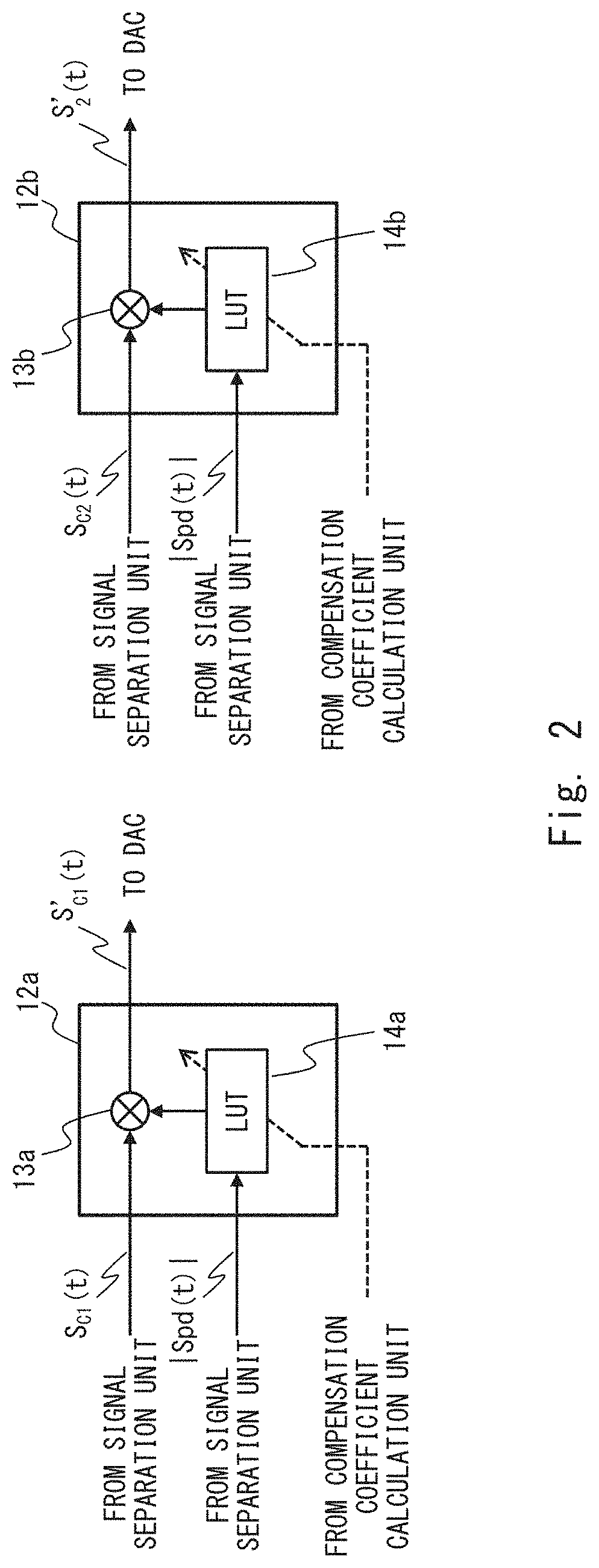
In an amplification apparatus according to the present disclosure, a combining unit combines an output signal of a first amplifier provided at a first branch with an output signal of a second amplifier provided at a second branch and outputs the combined signal. A non-linearity compensation unit multiplies an input baseband signal by a non-linearity compensation coefficient for compensating non-linearity of the entire apparatus, a first deviation compensation unit multiplies a first branch signal by a first deviation compensation coefficient for compensating an inter-branch deviation, and a second deviation compensation unit multiplies a second branch signal by a second deviation compensation coefficient for compensating the inter-branch deviation. A compensation coefficient calculation unit calculates the non-linearity compensation coefficient, the first deviation compensation coefficient, and the second deviation compensation coefficient based on the input baseband signal and a feedback baseband signal obtained by feeding back the combined signal.

Description

TECHNICAL FIELD[0001]The present disclosure relates to a technique for improving efficiency of a transmission apparatus such as a base station used in a radio communication system. In particular, the present disclosure relates to a technique for improving efficiency of an amplification apparatus, and a control technique therefor.BACKGROUND ART[0002]In related art, an outphasing type amplification apparatus (hereinafter referred to as an outphasing amplification apparatus) has been proposed as a high efficiency amplification apparatus that operates an amplifier in an output saturation region (see, for example, Non Patent Literature 1).[0003]The outphasing amplification apparatus is a linear amplification apparatus using a constant amplitude amplifier such as a saturation amplifier like an amplification apparatus of LINC (Linear Amplification with Nonlinear Components) type. However, the LINC type amplification apparatus uses, for example, a hybrid or 3 dB coupler which causes a loss ...

Claims


Application Information

Patent Timeline
Patent Type & Authority Applications(United States)
IPC IPC(8): H03F1/02
CPCH03F1/025H03F1/26H03F1/0294H03F3/24
Inventor DOI, YOSHIAKI
Owner NEC CORP
Learn More