
Semiconductor device

a technology of semiconductor devices and semiconductors, applied in semiconductor devices, electronic switching, pulse techniques, etc., can solve problems such as negative impact on radiation tolerance, and achieve the effect of maintaining radiation tolerance and reducing power consumption

Active Publication Date: 2020-01-02
MITSUBISHI HEAVY IND LTD +1
View PDF2 Cites 5 Cited by
  • Summary
  • Abstract
  • Description
  • Claims
  • Application Information

AI Technical Summary

Benefits of technology

The present invention aims to provide a technology that can reduce power consumption and maintain the ability of an SOI device to withstand radiation.

Problems solved by technology

According to the inventors' study, an inappropriate substrate bias voltage may cause a negative impact on the radiation tolerance.

Method used


Image

  • Semiconductor device
  • Semiconductor device
  • Semiconductor device

Examples


Embodiment Construction

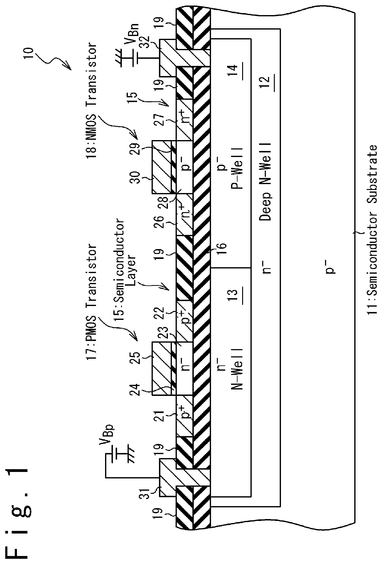
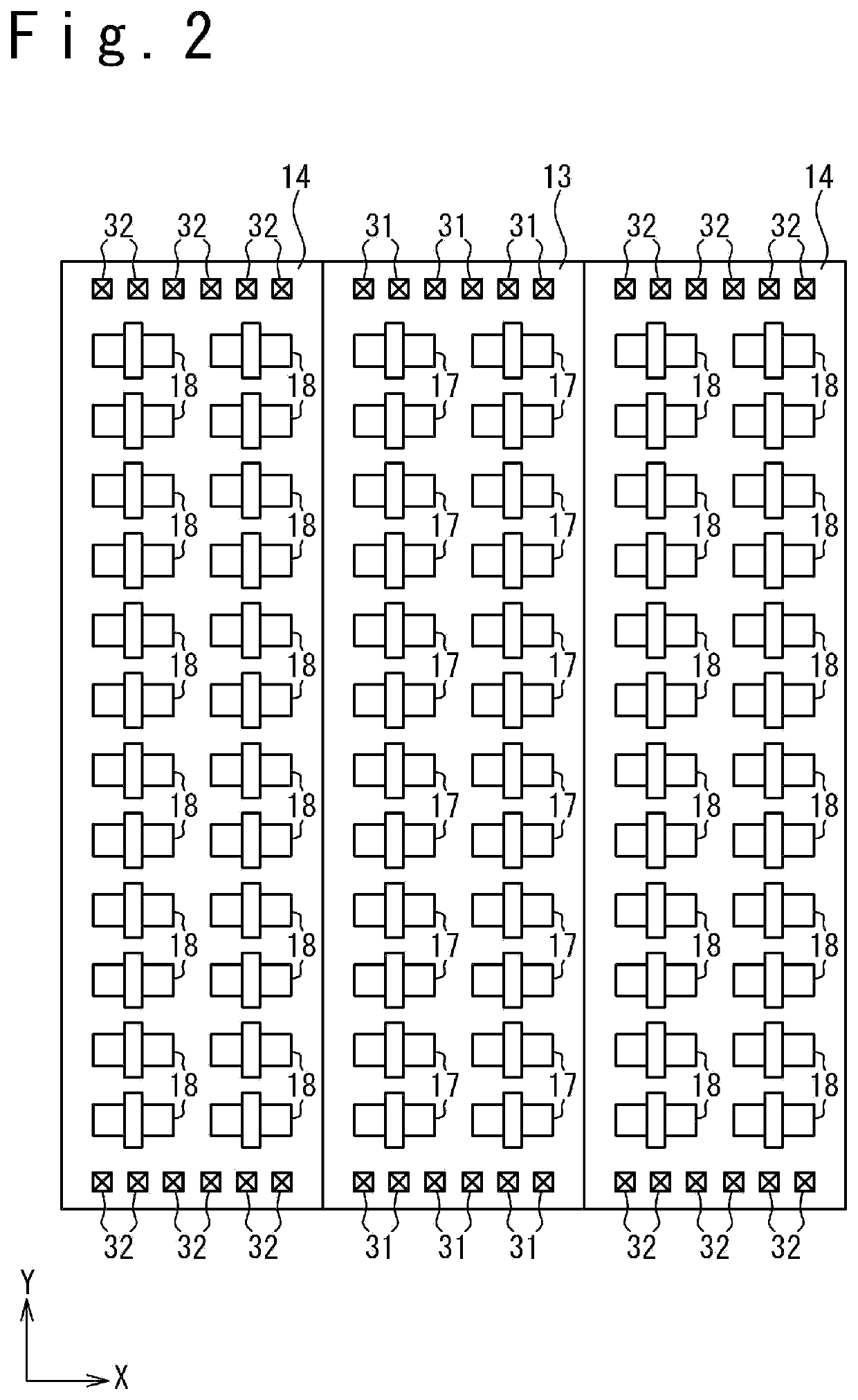
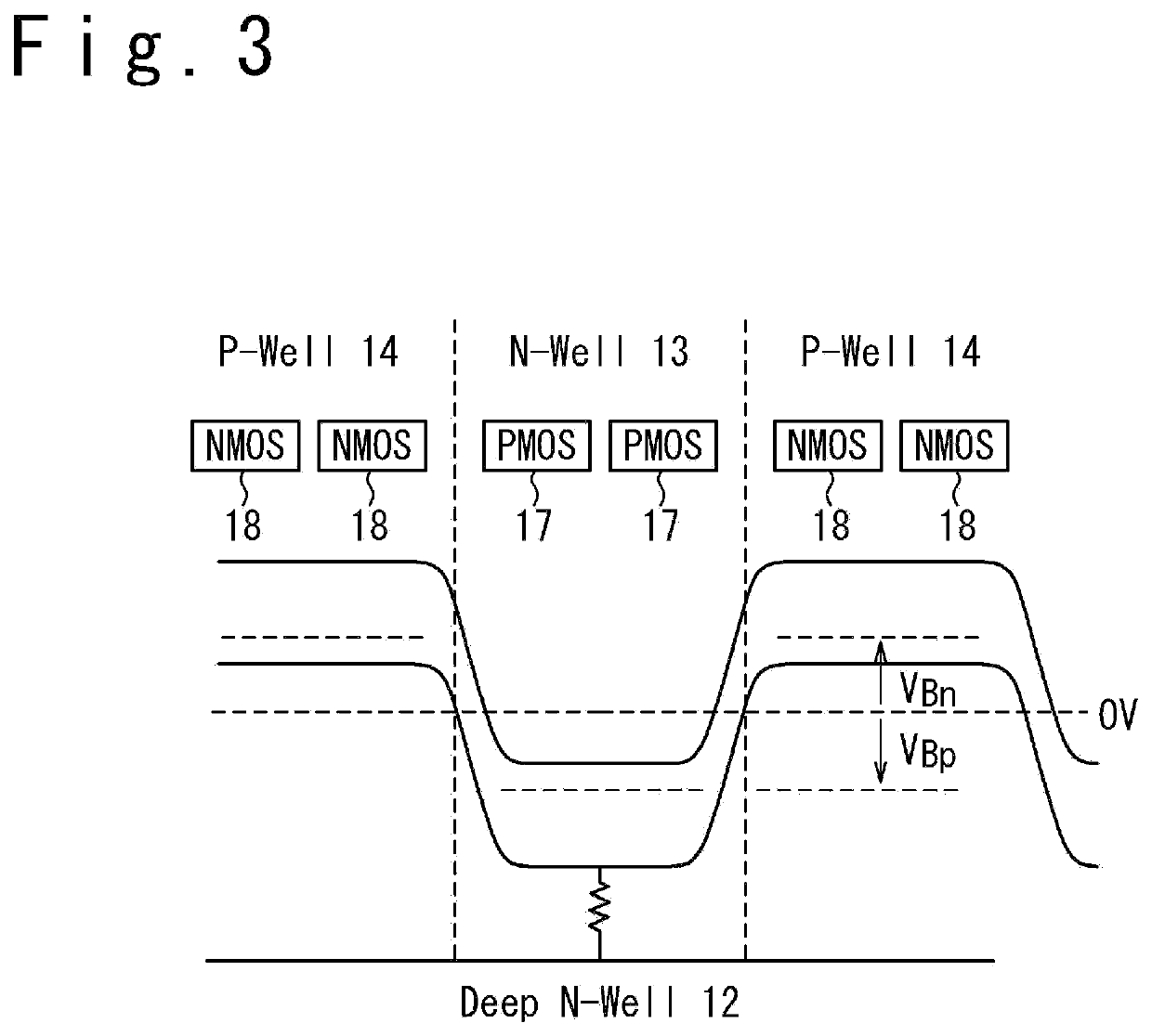
[0026]FIG. 1 is a section view illustrating the configuration of a semiconductor device 10, according to one embodiment of the present invention. The semiconductor device 10 according to this embodiment is configured as an SOI device. More specifically, a deep N-well 12 is formed in a semiconductor substrate 11, and an N-well 13 and a P-well 14 are formed in the deep N-well 12. In this embodiment, a p-type substrate is used as the semiconductor substrate 11. Alternatively, an n-type substrate may be used as the semiconductor substrate 11. The deep N-well 12 and the N-well 13 comprise n-type semiconductor regions doped with n-type impurities, and the P-well 14 comprises a p-type semiconductor region doped with p-type impurities. The N-well 13 and the P-well 14 are adjacent to each other and a pn junction is formed at the boundary between the N-well 13 and the P-well 14.

[0027]A semiconductor layer 15 is formed in the surface portion of the semiconductor substrate 11, and a buried oxid...


PUM

PropertyMeasurementUnit
source-gate voltageaaaaaaaaaa
bias voltageaaaaaaaaaa

Abstract

An operation adjustment method of an SOI device comprises steps of: (a) obtaining a drain current-substrate bias voltage characteristic of an NMOS transistor for a source-gate voltage of 0V; (b) obtaining a lowest substrate bias voltage which turns on the NMOS transistor from the drain current-substrate bias voltage characteristic; (c) determining an upper limit of a substrate bias voltage of a PMOS transistor as a voltage obtained by subtracting a built-in potential of a pn junction from the lowest substrate bias voltage; and (d) determining the substrate bias voltage of the PMOS transistor as a positive voltage lower than the upper limit. Reduction in the power consumption and maintenance of the radiation tolerance are both achieved for the SOI device.

Description

TECHNICAL FIELD[0001]The present invention relates to a semiconductor device and an operation adjustment method thereof, more particularly, to control of a substrate bias voltage of a semiconductor device using a silicon-on-insulator (SOI) technology.BACKGROUND ART[0002]The SOI technology is widely used as a technology for improving the operation speed of a semiconductor device and reducing the power consumption. In a semiconductor device using an SOI technology (which may be simply referred to as “SOI device”, hereinafter), a dielectric layer (buried dielectric layer) is formed under a channel of an MOS transistor, and this effectively reduces the parasitic capacitance of the MOS transistor. Accordingly, use of the SOI technology achieves rapid operation speed and reduced power consumption.[0003]To further reduce power consumption, technologies to control substrate bias voltages of SOI devices have been studied. An approach to reduce power consumption through substrate bias voltage...

Claims


Application Information

Patent Timeline
Patent Type & Authority Applications(United States)
IPC IPC(8): H03K17/687H01L27/092H01L21/8238
CPCH03K17/6872H01L21/8238H01L27/0928H01L27/08H01L27/088H01L27/092H01L27/1203H01L21/84H01L29/78648
Inventor MATSUURA, DAISUKENARITA, TAKANORIKATO, MASAHIROKOBAYASHI, DAISUKEHIROSE, KAZUYUKIKAWASAKI, OSAMUKAKEHASHI, YUYAITO, TAICHI
Owner MITSUBISHI HEAVY IND LTD
Learn More