Barrel with rifling and method for forming

a barrel and rifling technology, applied in the field of barrels, can solve the problems of increasing production difficulty and cost, limiting the caliber of the barrel than can be produced using rifling using conventional processes, and difficult or expensive production of conventional rifling for the barrel. to achieve the effect of ready-to-form

Active Publication Date: 2020-01-02
GARDNER & GARDNER REALTY CO INC
View PDF11 Cites 3 Cited by
  • Summary
  • Abstract
  • Description
  • Claims
  • Application Information

AI Technical Summary

Benefits of technology

[0005]According to various embodiments and principles of the present invention, a barrel for a pneumatic gun or firearm can provide numerous improvements over the prior art. More particularly, the principles of the present inventive concepts enable a barrel having rifling formed from an exterior of the barrel during an extrusion and / or drawing process and a method of forming the same. More particularly, a rifling pattern can be provided by rifling ridges formed on an inside diameter of the barrel during an extrusion and / or drawing process. The rifling ridges may be formed, for instance, on the inside of the barrel by impressing corresponding features into an external diameter of a tube (or tubing) during an extrusion or drawing process. This process is mainly suitable for aluminum (or similar material) barrels that can be readily formed through an extrusion process.

Problems solved by technology

Unfortunately, conventional rifling for a gun barrel may be difficult or expensive to produce.
In this process, each barrel must be individually rifled as a separate and individual part, increasing the production difficulty and costs.
Furthermore, because of limitations on the internal diameter (ID) tooling used in the conventional drawing process for forming rifling, there are limits to the caliber of the barrel than can be produced having rifling using conventional processes.
Specifically, traditional processes are generally unable to form a rifled barrel having very small calibers.

Method used


Image

  • Barrel with rifling and method for forming
  • Barrel with rifling and method for forming
  • Barrel with rifling and method for forming

Examples


Embodiment Construction

[0026]Various features, benefits, and configurations incorporating the principles of the present inventive concepts will be readily apparent through the illustrative embodiments shown in the accompanying drawings. Additional features, benefits, and configurations will be readily apparent to those of ordinary skill in the art based on this disclosure, and all such features, benefits, and configurations are considered within the scope of the present invention. Illustrative embodiments will now be described in further detail in connection with the accompanying drawings.

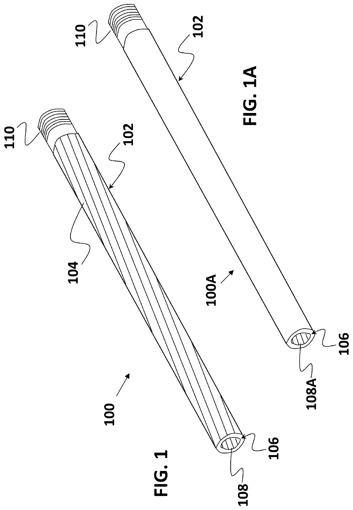
[0027]Referring initially to FIG. 1, in one embodiment, a barrel 100 may be formed having rifling ridges 108 arranged along an interior surface (or diameter) 106 of the barrel by impressing corresponding features 104 into an external surface (or diameter) 102 of the barrel 100. Rifling is thereby provided by ridges 108 along an internal diameter 106 of the barrel 100 that correspond to the indentations 104 formed into th...


PUM


Abstract

A rifled barrel may have a rifling pattern formed along an internal surface of the barrel by forming a corresponding pattern on the external surface of the barrel. The rifling pattern includes one or more indentations or protrusions formed in a spiral pattern along a length of the barrel. The corresponding pattern includes indentations formed into the external surface. A method of manufacturing includes moving a length of tubing past a die or other tool having one or more protrusions configured to indent the external surface. Alternatively, the rifled pattern may be formed by drawing a tool through tubing before it is cut into individual barrel lengths. The tool or tubing is rotated to create one or more spiral indentations and/or protrusions in a rifling pattern along the internal diameter of the tubing. The tubing is then cut and provided with threading to form a rifled barrel.

Description

PRIORITY CLAIMClaim for Priority[0001]This application is a non-provisional of, and claims priority from, U.S. Provisional Patent App. Ser. No. 62 / 692,997, filed Jul. 2, 2018, the contents of which are incorporated herein by reference, in their entirety.BACKGROUND OF THE INVENTIONField of the Invention[0002]This invention relates generally to barrels for paintball and other pneumatic guns, as well as to barrels for firearms. More particularly, this invention relates to a barrel having rifling formed therein and the method of forming the same.Related Art[0003]Pneumatic guns such as paintball guns, airsoft guns, bb guns, pellet guns, and the like, use barrels to direct the projectile from the gun toward the target. Spin may be imparted to the projectiles through air ports or rifling formed in the barrel. Firearms also typically have rifled gun barrels. Unfortunately, conventional rifling for a gun barrel may be difficult or expensive to produce. For instance, rifling is typically cut ...

Claims


Application Information

Patent Timeline
Patent Type & Authority Applications(United States)
IPC IPC(8): F41A21/18
CPCF41A21/18
Inventor GARDNER, JR., WILLIAM M.SEMELSBERGER, HANS
Owner GARDNER & GARDNER REALTY CO INC
Why Eureka
Try Eureka