Laser device

a laser device and laser technology, applied in lasers, laser details, laser cooling arrangements, etc., can solve the problems of laser medium vibration, first laser medium and second laser medium may vibrate, and reduce the accuracy of optical path control. , the effect of improving the gain characteristics

Active Publication Date: 2019-12-05
HAMAMATSU PHOTONICS KK
View PDF4 Cites 0 Cited by
  • Summary
  • Abstract
  • Description
  • Claims
  • Application Information

AI Technical Summary

Benefits of technology

[0012]According to the present disclosure, it is possible to provide a laser device capable of suppressing degradation of accuracy of optical path control while improving gain characteristics by cooling.

Problems solved by technology

In this refrigerator, vibration due to compression and expansion of the refrigerant is generated.
Therefore, there is concern that vibration may be generated in the laser medium due to transmission of the vibration in the refrigerator to the laser medium.
Therefore, there is concern that the first laser medium and the second laser medium may vibrate due to vibration due to the change in volume of the refrigerant.

Method used


Image

  • Laser device
  • Laser device
  • Laser device

Examples


Embodiment Construction

[0029]Hereinafter, an embodiment will be described in detail with reference to the drawings. In the drawings, the same elements or corresponding elements may be denoted by the same reference numerals, and redundant description may be omitted.

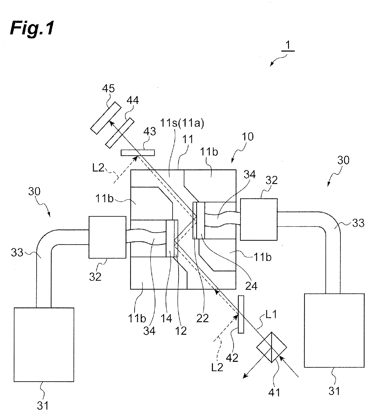
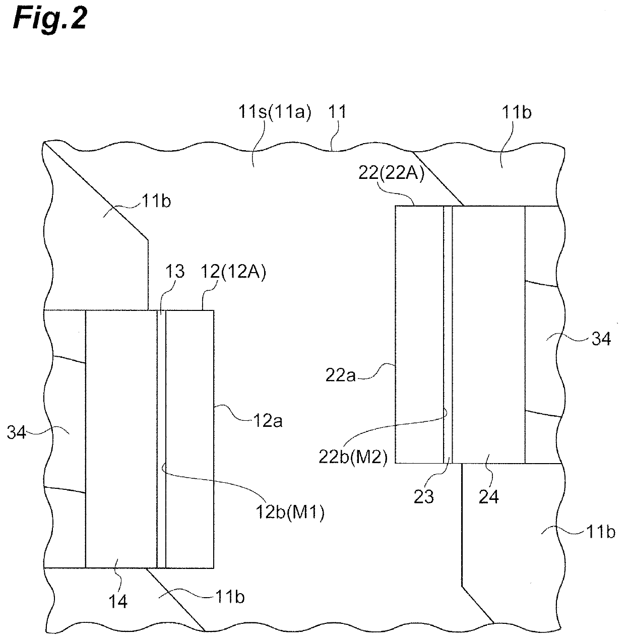
[0030]FIG. 1 is a schematic diagram illustrating an entire configuration of a laser device according to the embodiment. FIG. 2 is an enlarged view of main parts of FIG. 1. As illustrated in FIGS. 1 and 2, a laser device 1 includes an amplification unit 10 and a pair of cooling units 30. The amplification unit 10 includes a holder 11, a first laser medium 12, and a second laser medium 22. The holder 11 holds the first laser medium 12 and the second laser medium 22. The cooling unit 30 cools each of the first laser medium 12 and the second laser medium 22.

[0031]The first laser medium 12 includes a first surface 12a and a second surface 12b opposite to the first surface 12a. The first laser medium 12 receives seed light L1 and an input of excitatio...


PUM


Abstract

A laser device includes a first laser medium and a second laser medium that have a first surface and a second surface opposite to the first surface, and receive input of excitation light and seed light from the first surface side to amplify the seed light, a holder that holds the first laser medium and the second laser medium; and a pair of cooling units that cool the first laser medium and the second laser medium according to change in volume of a refrigerant.

Description

TECHNICAL FIELD[0001]The present disclosure relates to a laser device.BACKGROUND[0002]A laser device is described in Japanese Unexamined Patent Publication No. 2005-327857. This laser device includes a resonance type laser amplifier, and a path type laser light amplifier (multipath amplifier) for further amplifying laser light amplified by the resonance type laser amplifier. The path type laser light amplifier includes a laser medium and six reflective plates that form optical paths of laser light. The optical paths formed by the reflective plates are all configured to pass through the laser medium. Laser light from the resonance type laser amplifier is reflected by reflective plates one after another such that the laser light passes through a number of optical paths and is output. The laser light passes through the laser medium each time the laser light passes through these optical paths. The laser light is amplified each time the laser light passes through the laser medium.SUMMARY...

Claims


Application Information

Patent Timeline
Patent Type & Authority Applications(United States)
IPC IPC(8): H01S3/04H01S3/042H01S3/02H01S3/07H01S3/10H01S3/08
CPCH01S3/10007H01S3/025H01S3/042H01S3/10092H01S3/0407H01S3/08059H01S3/07H01S3/2316H01S3/0404H01S3/0405H01S3/0604H01S3/0621H01S3/1618H01S3/1643H01S3/2333H01S2301/02
Inventor IYAMA, KOICHITAKEUCHI, YASUKIHATANO, YUMAMORITA, TAKAAKIIGUCHI, TAKUTOKATO, YOSHINORISEKINE, TAKASHI
Owner HAMAMATSU PHOTONICS KK
Why Eureka
Try Eureka