Antenna apparatus

A technology of an antenna device and an antenna box, which is applied in directions such as antennas, resonant antennas, and antenna components, can solve problems such as damage to vehicle aesthetics, design, inability to obtain electrical characteristics, and deterioration of radiation directivity characteristics of planar antenna components 235, and achieve good gain. Effects of Features

Inactive Publication Date: 2014-04-23
HARADA IND CO LTD
View PDF6 Cites 0 Cited by
  • Summary
  • Abstract
  • Description
  • Claims
  • Application Information

AI Technical Summary

Problems solved by technology

[0006] In such a conventional antenna device 101, there is a problem that the appearance and design of the vehicle are damaged due to the rod-shaped portion protruding greatly from the vehicle body, and the rod-shaped portion may be damaged if the rod-shaped portion is forgotten to be put down during storage or car washing. loss of antenna performance
The reason is that the installation height of the planar antenna part 235 on the amplifier substrate 234 becomes high, the distance between the ground and the chip element of the planar antenna part 235 becomes large, and the electrical characteristics of the planar antenna part, especially the radiation Directionality brings influence
Furthermore, in the radiation field of the planar antenna part 235, there is an antenna element 231, which is a large metal body of about 1 / 2 wavelength of the operating frequency of the planar antenna part 235, in the low-elevation angle radiation range. Influenced by reflection, diffraction, etc., the radiation directivity characteristic of the planar antenna part 235 tends to deteriorate significantly
In this way, there is a problem that when an antenna is embedded in an antenna device having an antenna case with only a limited space, it is affected by the existing antenna and cannot obtain good electrical characteristics.

Method used


Image

  • Antenna apparatus
  • Antenna apparatus
  • Antenna apparatus

Examples


Embodiment Construction

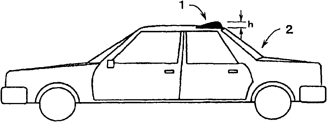
[0073] figure 1 A structure of a vehicle mounted with an antenna device according to an embodiment of the present invention is shown. like figure 1 As shown, the antenna device 1 of the first embodiment of the present invention is installed on the roof of a vehicle 2, and the height h protruding from the vehicle 2 is about 75 mm or less, preferably about 70 mm or less. The antenna device 1 of the first embodiment includes an antenna box described later and has an extremely low profile, but can receive AM broadcast, FM broadcast, and satellite radio broadcast. The antenna device 1 has a shape that becomes thinner toward the front end, and has a streamlined curved side surface that tapers inward, so as not to detract from the appearance and design of the vehicle. In addition, the lower surface of the antenna device 1 has a shape matching the shape of the mounting surface of the vehicle 2, and is mounted on the vehicle 2 in a waterproof manner.

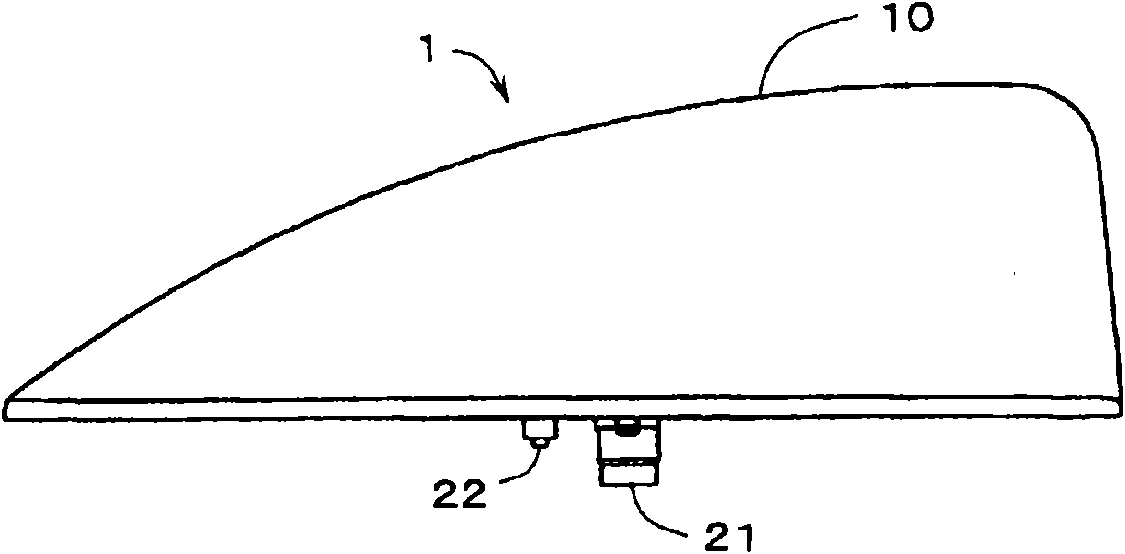
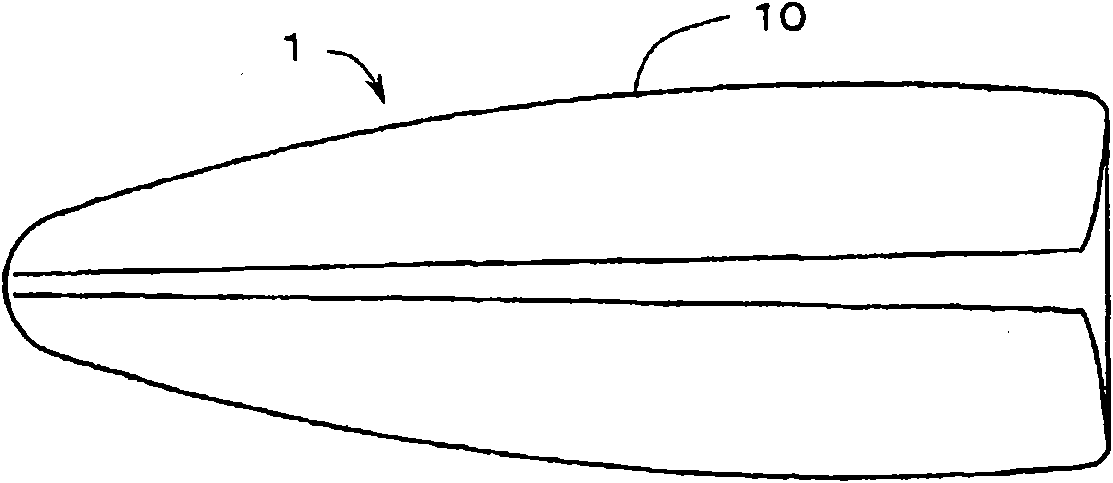
[0074] Next, Figure 2 to F...


PUM


Abstract

Good electric characteristics are obtained even after an antenna being further incorporated into an antenna apparatus including an antenna case having a limited space. An antenna device 31 is formed on an antenna substrate 30 installed upright in an antenna base 20. A flat antenna unit 35 is fastened to the antenna base 20 so that the flat antenna unit 35 is immediately below the antenna device 31. If the wavelength of a center frequency in an operating frequency band of the flat antenna unit 35 is », an interval between an upper surface of the flat antenna unit 35 and a lower end of the antenna device 31 is set to about 0.25» or more. Accordingly, it becomes possible to make directional characteristics of radiation in a horizontal plane of the flat antenna unit 35 non-directive without being affected by the antenna device 31 and also to achieve good gain characteristics.

Description

technical field [0001] The present invention relates to a low profile antenna device installed in a vehicle capable of receiving at least FM broadcasts. Background technique [0002] Conventional antenna devices mounted on vehicles are generally configured as antenna devices capable of receiving AM broadcasts and FM broadcasts. In a conventional antenna device, a rod antenna with a length of about 1 m is used for receiving AM broadcast and FM broadcast. The length of this rod antenna is approximately 1 / 4 wavelength in the FM band, but is very short relative to the wavelength in the AM band, so its sensitivity is remarkably reduced. Therefore, conventionally, the rod antenna is made high impedance for the AM band using a high-impedance cable, or is amplified using an AM band amplifier to ensure sensitivity. In addition, there is also used a vehicle-mounted antenna device in which the length of the antenna is shortened to approximately 180 mm to 400 mm by using a helical ant...

Claims


Application Information

Patent Timeline
Patent Type & Authority Patents(China)
IPC IPC(8): H01Q9/30H01Q1/32H01Q1/42H01Q21/30
CPCH01Q1/3275H01Q1/42H01Q21/30H01Q1/32H01Q9/30
Inventor 大岛元树井上仁一泉井将史荒山修男
Owner HARADA IND CO LTD
Why Eureka
Try Eureka