
Reference signal with beamforming training and channel estimation

a beamforming training and channel estimation technology, applied in the field of wireless communication, can solve the problems of large system overhead, large propagation and/or path loss of radio channels,

Active Publication Date: 2019-11-28
NOKIA TECHNOLOGLES OY
View PDF0 Cites 2 Cited by
  • Summary
  • Abstract
  • Description
  • Claims
  • Application Information

AI Technical Summary

Benefits of technology

The patent is about a device that can receive a reference signal for demodulation and beamforming training, and use it to simultaneously estimate the channel and perform beamforming training. This results in more efficient use of the reference signal and faster data transmission.

Problems solved by technology

Higher carrier frequencies, such as 28 GHz, may lead to large propagation and / or path loss of a radio channel.
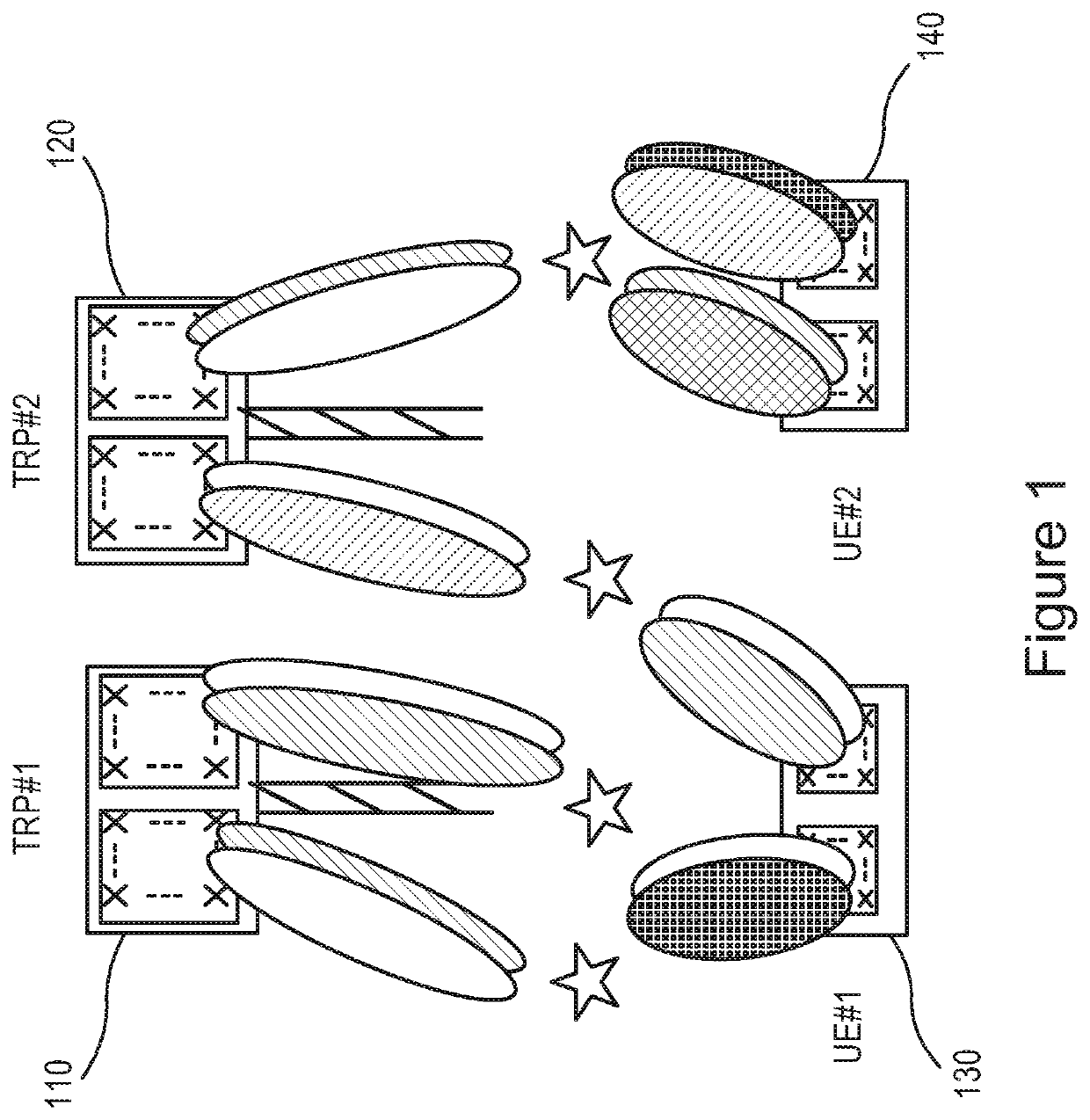
Using such methods to exploit the full merit of the arrays, however, may lead to a large amount of system overhead caused by performing functions such as beamforming training, beam tracking, and beam switching at a user equipment.

Method used


Image

  • Reference signal with beamforming training and channel estimation
  • Reference signal with beamforming training and channel estimation
  • Reference signal with beamforming training and channel estimation

Examples


first embodiment

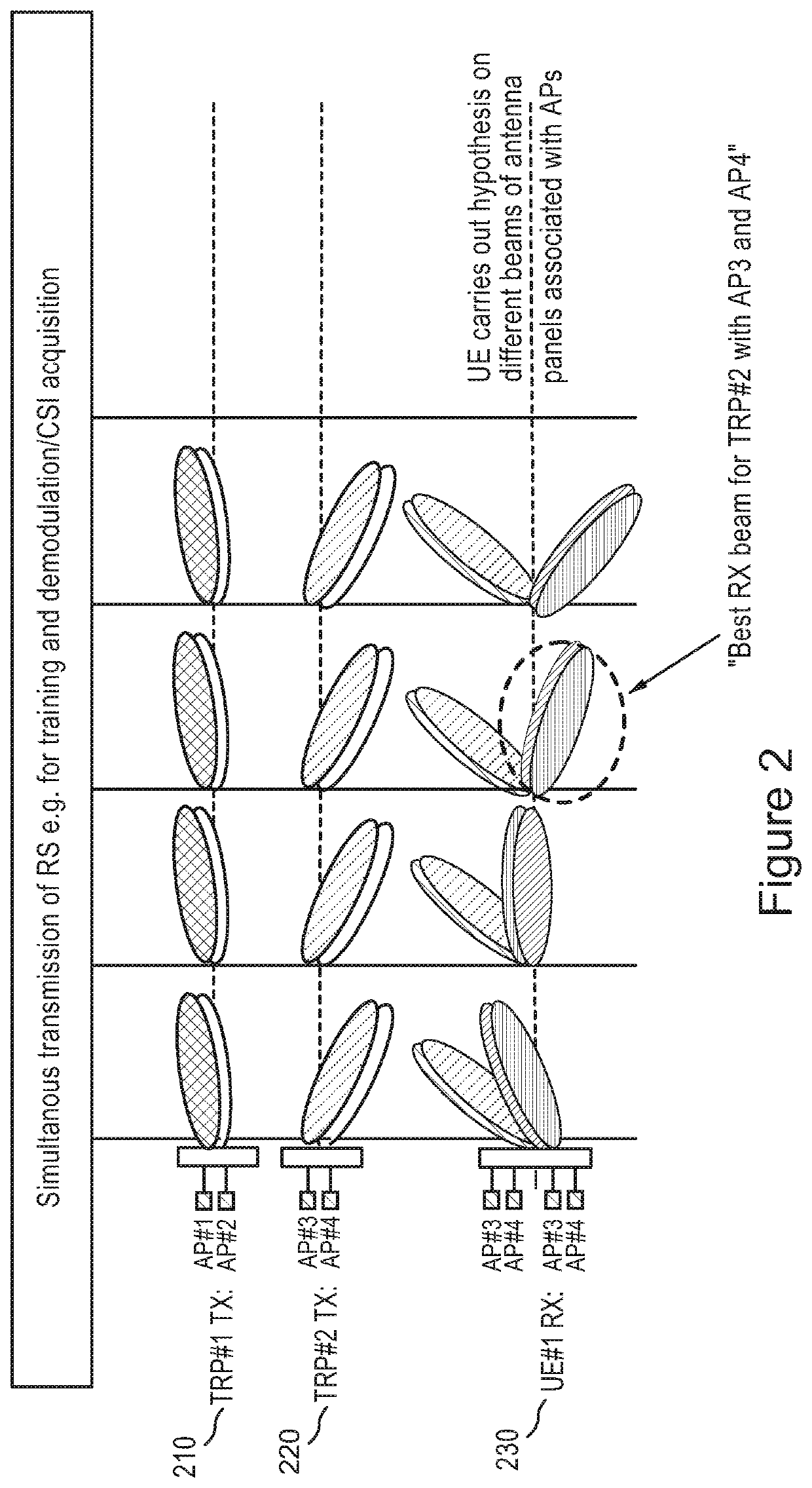
[0084] a method may include receiving at a user equipment a multi-numerology joint reference signal. The reference signal comprises a reference signal for data channel demodulation or channel state information acquisition, and a reference signal for beamforming training. The method may also include performing simultaneous beamforming training and channel estimation or channel state information acquisition based on the multi-numerology joint reference signal.

[0085]In a variant, the user equipment may receive an indication that multiple antenna ports are set to detect a multi-numerology reference signal.

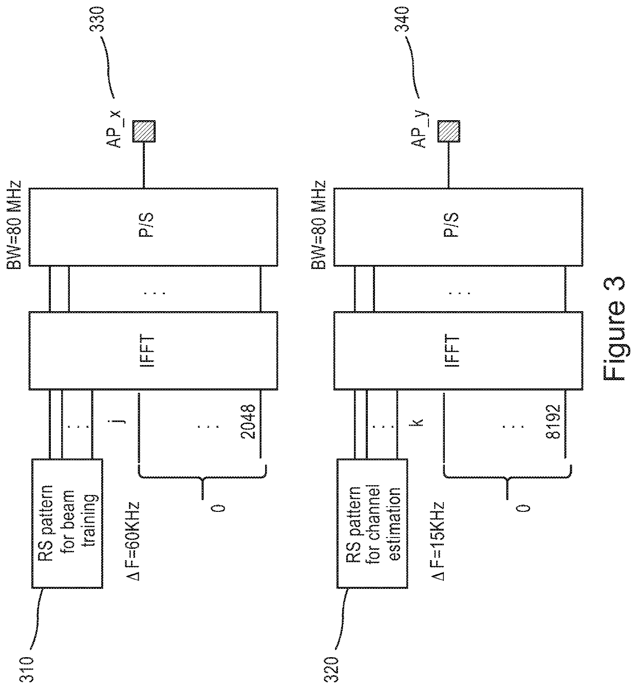
[0086]In another variant, the user equipment may receive an indication that a first numerology in the multi-numerology reference signal is intended for beamforming training, and a second numerology in the multi-numerology reference signal is intended for channel estimation or channel state information acquisition.

[0087]In yet another variant, the channel estimation may include an estim...

second embodiment

[0093] a method may include preparing at the network node a multi-numerology joint reference signal. The reference signal comprises a reference signal for data channel demodulation or channel state information acquisition, and a reference signal for beamforming training. The method may also include sending the multi-numerology joint reference signal to a user equipment.

[0094]In a variant, the sending of the multi-numerology joint reference signal may be triggered by at least one of receiving feedback or a request from a user equipment or a predetermined triggering condition at the network node.

[0095]In another variant, the beamforming training pattern and information relating to demodulation of the data channel or channel state information acquisition may be simultaneously transmitted within a single orthogonal frequency-division multiplexing symbol.

[0096]In an additional variant, the multi-numerology reference signal is prepared on different antenna ports of the network node.

[0097]...


PUM


Abstract

Various communication systems may benefit from improved signaling. For example, communication systems may benefit from sending a multi-numerology reference signal that allows a receiving user equipment to perform simultaneous beamforming training, and channel estimation or channel state information acquisition. A method may include receiving at a user equipment a multi-numerology joint reference signal (610). The reference signal may include a reference signal for data channel demodulation or channel state information acquisition, and beamforming training. The method may also include performing simultaneous beamforming training and channel estimation or channel state information acquisition based on the multi-numerology joint reference signal (620).

Description

CROSS REFERENCE TO RELATED APPLICATION[0001]This application claims priority to U.S. Provisional Application No. 62 / 403,522 filed on Oct. 3, 2016. The entire content of the above-referenced provisional application is hereby incorporated by reference.BACKGROUNDField[0002]The described invention relates to wireless communications, and more particularly to a reference signal for 5G New Radio systems.Description of the Related Art[0003]Third generation partnership project (3GPP) 5th generation (5G) technology is a new generation of radio systems and network architecture that can deliver extreme broadband and ultra-robust, low latency connectivity. 5G can provide for a digital-analog hybrid antenna architecture used at a base station and a user equipment. The hybrid antenna can help to facilitate system targeting for higher carrier frequencies that are greater than 6 gigahertz (GHz).[0004]Higher carrier frequencies, such as 28 GHz, may lead to large propagation and / or path loss of a radi...

Claims


Application Information

Patent Timeline
IPC IPC(8): H04B7/06H04L5/00H04W16/28
CPCH04B7/0626H04B7/0617H04W16/28H04B7/0695H04L5/0094H04L5/0051H01Q3/2605H04B7/088H04L5/0007H04L5/0023H04L5/005H04L5/0053H04L5/0064H04B7/0639H04B7/0632G01S3/42
Inventor KARJALAINEN, JUHA PEKKAENESCU, MIHAIPAJUKOSKI, KARI PEKKAHAKQLA, SAMI-JUKKAKOSKELA, TIRRIO
Owner NOKIA TECHNOLOGLES OY
Learn More