
Device and Method for Reeling in a Cable from a Source and Temporarily Storing the Cable

a technology for storing and reeling in cables, which is applied in the direction of cable installation on the ground, cable laying vessels, cable apparatus, etc., can solve the problems of limited cable storage units such as cable carousels, limited quantity of cable that can be stored on board of vessels as one continuous length, and repairing or installing these connections involves an appreciable amount of time and money, so as to achieve the effect of increasing the total length of stored cables and improving efficiency

Pending Publication Date: 2019-11-28
DEME OFFSHORE NL BV
View PDF6 Cites 1 Cited by
  • Summary
  • Abstract
  • Description
  • Claims
  • Application Information

AI Technical Summary

Benefits of technology

The invention is a device that allows a cable laying vessel to store more continuous cable without the need for major modifications to the vessel. The device includes two storage units that can hold more cable without taking up deck space. The storage units can rotate around a cylinder longitudinal axis in a reeling direction to more efficiently store the cable. The device can also have multiple storage units of different sizes to increase efficiency. The technical effects of the device include improved cable laying operation and more efficient use of vessel space.

Problems solved by technology

Such cables desirably have as few connections as possible, since connections represent possible sources of interference or disruption in transmission of the signal.
Further, repairing or installing these connections involves an appreciable amount of time and money.
The quantity of cable that can be stored on board of a vessel as one continuous length is limited however.
Storage units for cables such as cable carousels for instance are limited in size because of space restrictions on board of a vessel.
Deck space is limited but building up cable carousels in the height direction is also limited for reasons of the required stability of the vessel.

Method used


Image

  • Device and Method for Reeling in a Cable from a Source and Temporarily Storing the Cable
  • Device and Method for Reeling in a Cable from a Source and Temporarily Storing the Cable
  • Device and Method for Reeling in a Cable from a Source and Temporarily Storing the Cable

Examples


Embodiment Construction

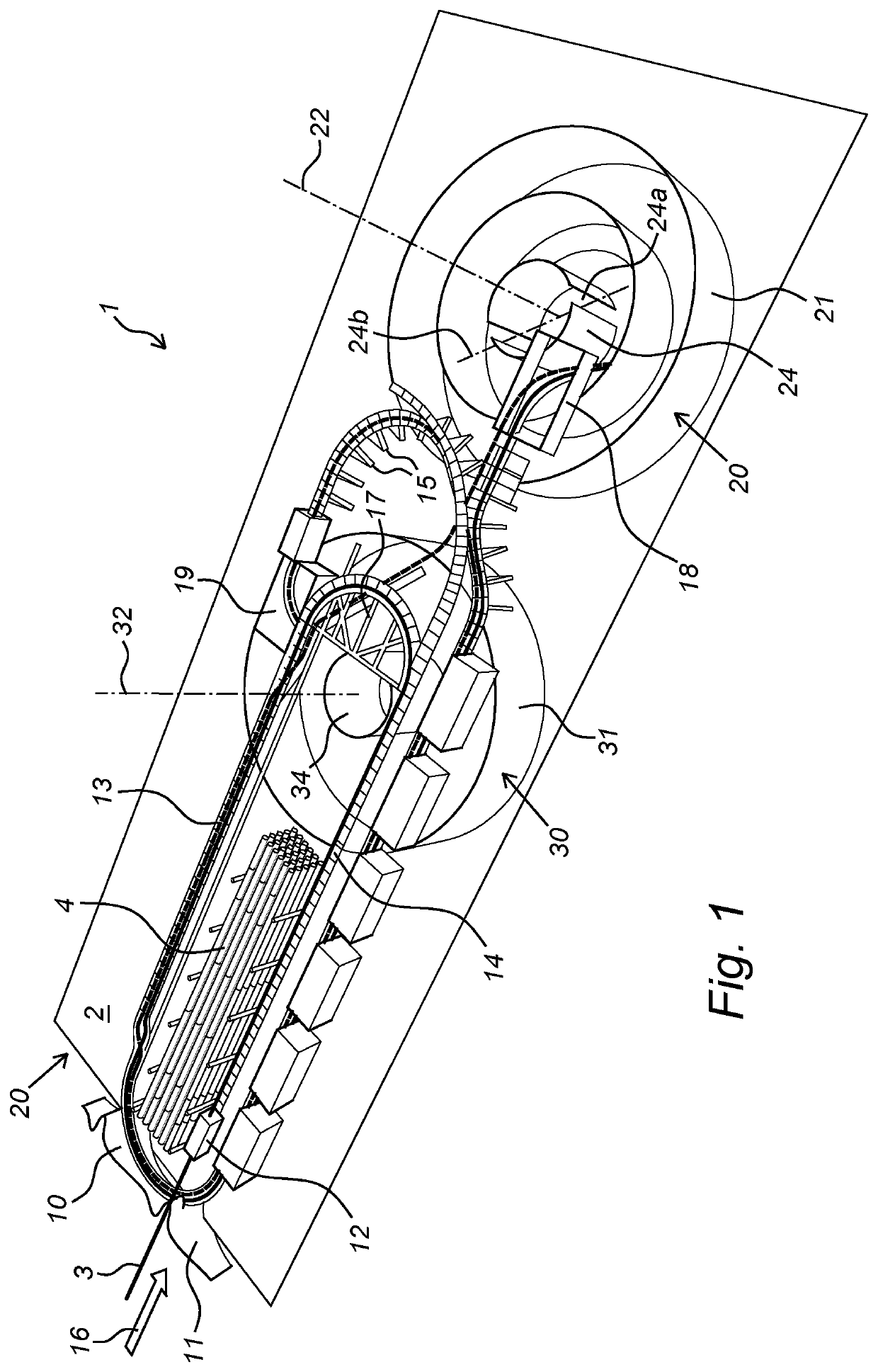
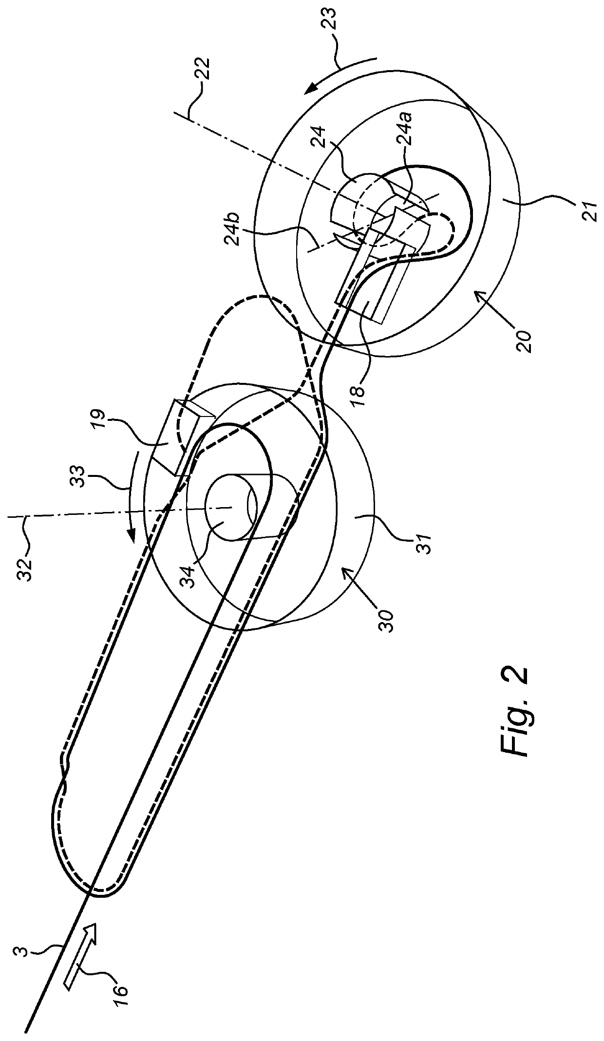
[0035]Referring to FIG. 1, a part of the deck 2 of a vessel 1 for laying cables 3 on or in a sea bed is shown. The vessel 1 is at a rear side 20 of the deck 2 provided with a portside chute 10 and a starboard chute 11 for guiding a cable 3. The chutes (10, 11) may be used to reel in a cable 3 from a suitable source, such as an onshore cable rack (not shown), but may also be used to bring out of board cable 3 during a cable laying operation off shore. A cable tensioner 12 may be present to pull the cable 3 along support means in the form of port side and starboard cable trays (13, 14). The cable trays (13, 14) are supported by poles 15 to elevate and hold the trays above work deck level. A cable 3 that is pulled in from shore in the direction 16 is first led along a so-called quadrant 17. This is also shown in FIG. 2. The quadrant structure 17 guides a cable 3 along an arc with a radius that is equal or larger than the minimum bending radius (MBR) of the cable 3, this in order to pre...


PUM


Abstract

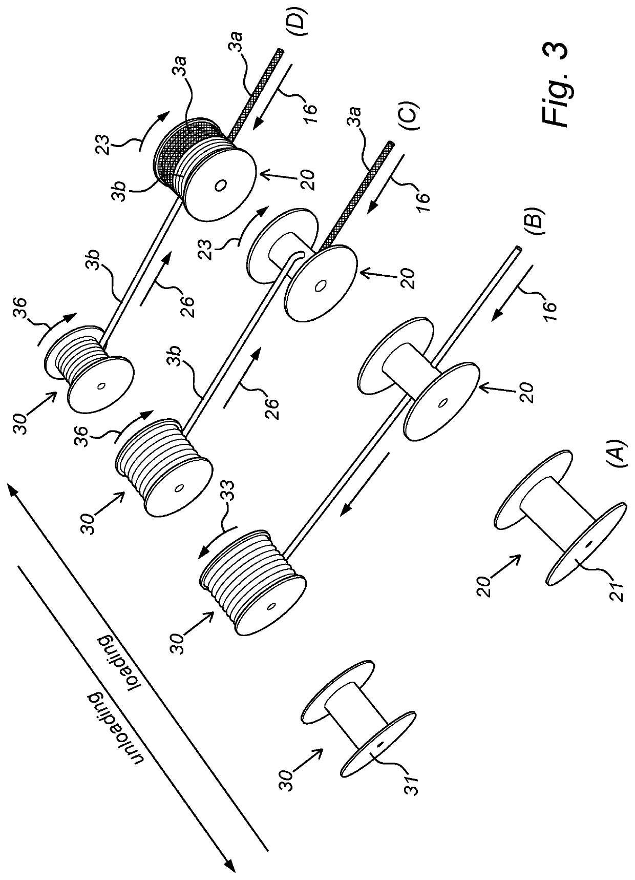
A device for reeling in a cable and temporarily storing the cable is described. The device comprises first and second storage units, each comprising a cylindrical body for arranging the cable, as well as support means for carrying the cable from the source to cable seizing means of the second storage unit and further to the first storage unit. The second storage unit is rotatable around a rotation axis parallel to the cylinder longitudinal axis in a reeling direction. The storage units are arranged such that the second storage unit when rotating in the reeling direction can simultaneously reel in a part of the seized cable originating from the source and another part of the seized cable originating from the first storage unit. A method for reeling in the cable is also described. The device and method allow storing an increased amount of cable on a cable laying vessel for instance.

Description

BACKGROUND OF THE INVENTION[0001]The present invention relates to a device for reeling in a cable from a source and temporarily storing the cable. The invention further relates to a floating structure comprising the device, to a method for reeling in a cable from a source and temporarily storing the cable, and to a method for laying a cable on or in a sea bed using the floating structure.[0002]There is an increasing demand for laying cables, such as data communication and electrical cables on or in a seabed or the bed of another body of water. Such cables desirably have as few connections as possible, since connections represent possible sources of interference or disruption in transmission of the signal. Further, repairing or installing these connections involves an appreciable amount of time and money.[0003]The quantity of cable that can be stored on board of a vessel as one continuous length is limited however. Storage units for cables such as cable carousels for instance are lim...

Claims


Application Information

Patent Timeline
IPC IPC(8): B63B35/04H02G1/10H02G9/02B65H75/08
CPCB65H75/08B65H75/4452H02G9/02B65H75/425H02G1/10B65H54/10B65H2701/34B63B35/04
Inventor GREMMEN, MARCO MARTINUS MARIAJASPERS, JEROENBOLS, LUCAS ADRIAAN MARIA
Owner DEME OFFSHORE NL BV
Learn More