
Cable winding device

A cable winding and cable routing technology, which is used in cable laying equipment, the arrangement of reels/photosensitive drums, etc., can solve the limitation of the operating depth of the underwater robot carrier, the limited length of the storage cable, and the high requirements of operators. problems, to achieve the effect of ensuring service life, compact structure, and increasing storage length

Inactive Publication Date: 2011-08-03
SHENYANG INST OF AUTOMATION - CHINESE ACAD OF SCI
View PDF0 Cites 0 Cited by
  • Summary
  • Abstract
  • Description
  • Claims
  • Application Information

AI Technical Summary

Problems solved by technology

For the realization of the ship crane, the operating depth of the underwater robot carrier is limited, and it is only suitable for the operation of small underwater robots. When performing retracting and retracting operations, multiple people are required to complete the task of retracting and retracting the cables, which is easy to damage the cables and requires labor. strong
For the implementation of the winch on the deck, the length of the existing winches to store cables is limited, and the cables are not evenly arranged. The cable laying method of the winch is realized manually, relying on the positive and negative rotation of the motor to realize the cable laying wheel The horizontal reciprocating motion of the machine is complicated, and requires the cooperation of multiple people to carry out the operation, and the requirements for the operator are high, and it is easy to cause mechanical failure due to operational errors.

Method used

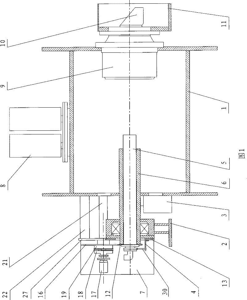

Image

  • Cable winding device
  • Cable winding device
  • Cable winding device

Examples


Embodiment Construction

[0020] The present invention will be described in further detail below in conjunction with the accompanying drawings.

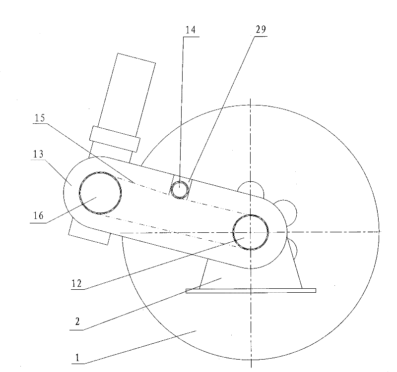
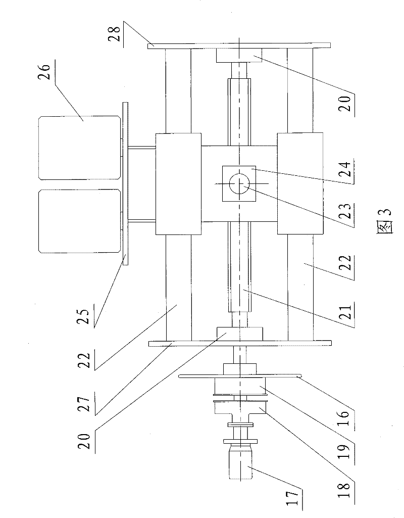
[0021] Such as Figure 1~3 As shown, the present invention includes a reel 1, a slip ring 5, a reel bushing 6, a cable router 8, a reducer 9 and a motor 10. There are round holes for installing the reel shaft sleeve 6 and the reducer 9 at the center of both ends of the cylinder 1, and the reel 1 on the side where the reel shaft sleeve 6 is installed is also provided with a process hole. The reel bushing 6 is coaxially installed on one end of the reel 1 through the center hole 1 at one end, and the reducer 9 is fixedly connected to the center hole 1 at the other end of the reel 1, and the motor 10 is fixedly connected to the end face of the reducer 9 Above, the reducer support 11 is sleeved on the outer surface of the reducer 9; a support 2 is sleeved on the reel shaft sleeve 6 outside the reel 1, and the outer end surface of the support 2 is fixedly connecte...


PUM


Abstract

The invention relates to an underwater robot operating device, in particular to a cable winding device capable of storing a cable with enough length and realizing launching and recovering of an underwater robot. The cable winding device comprises a winding drum, a slip ring, a winding drum axial sleeve, a cable laying machine, a reducer and a motor, wherein the winding drum axial sleeve is coaxially arranged at one end of the winding drum, and the motor is arranged at the other end of the winding drum by the reducer; a support seat is sleeved on the winding drum axial sleeve arranged outside the winding drum, the outer end face of the bracket is fixedly connected with a connecting plate, and the cable laying machine is arranged at the other end of the connecting plate; the slip ring is arranged in the winding drum axial sleeve, one end of the slip ring is fixedly connected with the winding drum axial sleeve, while the other end runs through out of the winding drum axial sleeve; the slip ring is connected with the cable laying machine by a chain wheel transmission mechanism, and a transmission pair of the slip ring forms a moving pair of the cable laying machine along the axial direction of the winding drum by the chain wheel transmission mechanism; and the winding drum is provided with a connection box on the part which is on the same side as the winding drum axial sleeve, andthe tail line of the slip ring is electrically connected with the cable and the connection box. The cable winding device has the advantages of automatic cable laying, smooth cable arrangement, easy and convenient operation and the like.

Description

technical field [0001] The invention relates to an underwater robot operating device, in particular to a cable winding device capable of storing cables of sufficient length and realizing release and recovery of the underwater robot. Background technique [0002] An underwater robot is a robot that works in an underwater environment. When an underwater robot is to perform underwater operations, it must be released to a certain depth underwater. When the underwater robot completes the underwater operation, it must be recovered to the deck. ; Release and recovery operations are the premise and guarantee for the underwater robot carrier to complete underwater operations. [0003] At present, for the retraction and deployment of the underwater robot, it is generally realized by a ship crane or a winch on the deck. For the realization of the ship crane, the operating depth of the underwater robot carrier is limited, and it is only suitable for the operation of small underwater ro...

Claims


Application Information

Patent Timeline
Patent Type & Authority Patents(China)
IPC IPC(8): H02G1/10H02G11/02B65H75/34
Inventor 张竺英任福琳
Owner SHENYANG INST OF AUTOMATION - CHINESE ACAD OF SCI
Learn More