
Analytical Tools and Method for Modeling Transport Processes in Fluids

a technology of fluids and analytical tools, applied in the field of analytical tools and methods for modeling transportation processes in fluids, can solve the problems of affecting the usefulness of computation results, affecting the accuracy of fluid modeling, so as to improve the time resolution of computations, increase the operable range of knudsen numbers, and expand the horizon of cfd applications

Inactive Publication Date: 2019-11-21
KISLOV NIKOLAI
View PDF0 Cites 1 Cited by
  • Summary
  • Abstract
  • Description
  • Claims
  • Application Information

AI Technical Summary

Benefits of technology

This approach allows for accurate modeling and computation of fluid flows in rarefied gases and improves time resolution for unstable flows, expanding the operational range of CFD to higher Knudsen numbers, reducing computational resources, and increasing prediction accuracy.

Problems solved by technology

Computational Fluid Dynamics (CFD) is used mainly for analytical predictions of the fluid transport properties, including velocity, heat transfer coefficient, and pressure; still, CFD has many challenges.
One challenge is that the users must select the appropriate models to characterize their specific problem.
However, errors due to uncertainty in the formulation of the model and often intentional simplification of the model may diminish the usefulness of the results of the computations.
Also, errors in the modeling of the fluids are disturbed with the choice of the governing equations to be solved and models for the fluid properties.
The general major disadvantage of any existing or available on market CFD software consists of using an infinitesimal fluid element viewed as a continuous medium, to which fundamental physical principles are applied.
This approach is in a contradiction with the molecular or particle nature, thus providing a source of significant uncertainty in interpreting the results of modeling and calculations.
Disadvantageously, this approach does not consider the dynamic behavior of the fluid system in times earlier than initial time, t0, which actually affects the behavior of the fluid system in times following the initial time.
Also, the balance equations can only describe fluid flow approximately mostly because of the inability to determine the functional distribution for viscous stress forces and the rate of heat addition and viscous dissipation.
Thus, although the conservation laws correctly describe the fluid within a control volume located remotely in a fluid flow, they do not take into consideration the molecular nature of the fluid.
As a general limitation, microscopic or bulk analysis allows the treatment of a collection of free particles as a continuum where collisional mean free path, λf, is much lower than the macroscopic length scale L of the system.
However, the classical continuum approach cannot be applied to situations when the length scale of the system is of the same order or less as compared to the collisional mean free path.
At the current state of the art, specifying the boundary conditions is one of the most difficult parts of the analysis.
The limitation that the NS equations are valid for Kn<0.01 reduces the fields of CFD applications significantly.
Specifically, the CFD method is inapplicable for modeling of dilute or rarefied gases.
It is not useful for simulations microelectronics and nanoelectronics low-pressure processing and plasma processing.
It does not simulate a gas flow properly in microchannels in micromechanical systems (MEMS) applications.
This method is enormously complicated and restricted because of the limitation of the available computational approaches for modeling real physical systems.

Method used


Image

  • Analytical Tools and Method for Modeling Transport Processes in Fluids
  • Analytical Tools and Method for Modeling Transport Processes in Fluids
  • Analytical Tools and Method for Modeling Transport Processes in Fluids

Examples


example 1

2.1 Simulation 1

[0427]In the first simulation, Simulation 1, transient plane Couette flow is calculated.

[0428]FIG. 6 is a schematic view in section of a Newtonian model gas between parallel infinite plates in the open channel at uniform temperature and no external field of force applied in y direction and a lack of internal aging processes, namely, λ=0, each particle conserves properties acquired by it at a point and time of the original collision and deliver that properties unchanged to another location upon its final collision with another particle in a point sink. The following simulation is shown to illustrate the inventive approach in determining velocity profiles ux(y,t) or velocity distribution across the space between the plates.

[0429]A simulation is performed for incompressible model gas expanding in the y-direction between parallel infinite plates being spaced at the distance H in the open channel at the uniform temperature where the top and bottom plates and the model ga...

example 2

2.2 Simulation 2

[0473]In the second simulation, Simulation 2, the steady velocity profile across between the parallel plates with mixed diffuse and specular particles scatterings from the plates being at rest is calculated.

[0474]The particular embodiment is limited to a simulation of incompressible stable model gas flow confined in the y-direction between parallel infinite plates at a uniform temperature with no external field of the force applied in y-direction where the top and bottom plates are at rest. However, the method can be generalized to the model gas flow affected by the external field of force or kept at non-uniform temperature with no difficulty, as apprehended by those skilled in the art. The pressure gradient is constant along with the model gas flow in he x-direction. The velocity profile induced in the model gas due to the pressure gradient is to be determined. Referring to FIG. 14, more detailed description of the steps of performing flow calculation by the comput...


PUM


Abstract

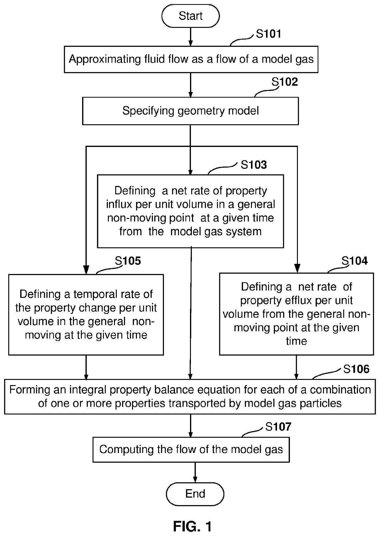
An improved computer implemented method for modeling transport processes in fluids is disclosed. The method is adapted to model gas flow including dilute gas flow at high Knudsen numbers. Instead of modeling based on using an infinitesimal fluid element of a continuous medium, the method approximates fluid flow as a model gas flow. The method is based on assuming that each of a plurality of particles, which compose the model gas, travels with a probability between any of two points in space occupied by the model gas by following a ballistic trajectory governed by a law of motion in free space and treating each of the plurality of ballistic particles as a property carrier transporting one or more of mass, momentum, and energy between the points of consecutive collisions. The major steps of the method are indicated in the accompanying flow chart. The method also delivers a new basis for prediction of dynamic evolution of the model gas system by considering a pre-established or known dynamic history of the system during a pre-initial period.

Description

TECHNICAL FIELD[0001]The present invention relates to an improvement of the computer implemented method for modeling transport processes in fluids.BACKGROUND ART[0002]Computational Fluid Dynamics (CFD) is used mainly for analytical predictions of the fluid transport properties, including velocity, heat transfer coefficient, and pressure; still, CFD has many challenges. One challenge is that the users must select the appropriate models to characterize their specific problem. However, errors due to uncertainty in the formulation of the model and often intentional simplification of the model may diminish the usefulness of the results of the computations. Also, errors in the modeling of the fluids are disturbed with the choice of the governing equations to be solved and models for the fluid properties. The sources of uncertainty in physical models are listed by Mehta, U. B. 1996, “Guide to Credible Computer Simulations of Fluid Flows,” AIAA Journal of Propulsion and Power 12, 5, 940-948...

Claims


Application Information

Patent Timeline
Patent Type & Authority Applications(United States)
IPC IPC(8): G06F17/50
CPCG06F17/5018G06F2217/16G06F17/13G06F30/23G06F2111/10G06F17/18
Inventor KISLOV, NIKOLAI
Owner KISLOV NIKOLAI
Learn More