
Suction forceps for endoscopic surgery

a technology of endoscopic surgery and suction force, applied in the field of suction forceps for endoscopic surgery, can solve the problems of longer operation period and larger bleeding amount, and achieve the effect of preventing the longer surgical period

Inactive Publication Date: 2019-11-21
SAKURAZAWA NOBUYUKI +1
View PDF0 Cites 1 Cited by
  • Summary
  • Abstract
  • Description
  • Claims
  • Application Information

AI Technical Summary

Benefits of technology

The invention is a suction forceps for endoscopic surgery that can quickly suction liquids such as blood without needing to re-insert a special suction pipe. This prevents bleeding or leaking body liquid during surgery, which can make the operation longer. The technical effect of this invention is to shorten the surgical period and improve the surgical field.

Problems solved by technology

Accordingly, the surgical field may not be ensured until insertion of the suction pipe and suction of the blood, therefore raising a problem to cause the bleeding amount larger resultantly and to make the operation period longer, because bleeding may not be suppressed until completion of a treatment stopping bleeding.

Method used


Image

  • Suction forceps for endoscopic surgery
  • Suction forceps for endoscopic surgery
  • Suction forceps for endoscopic surgery

Examples


first embodiment

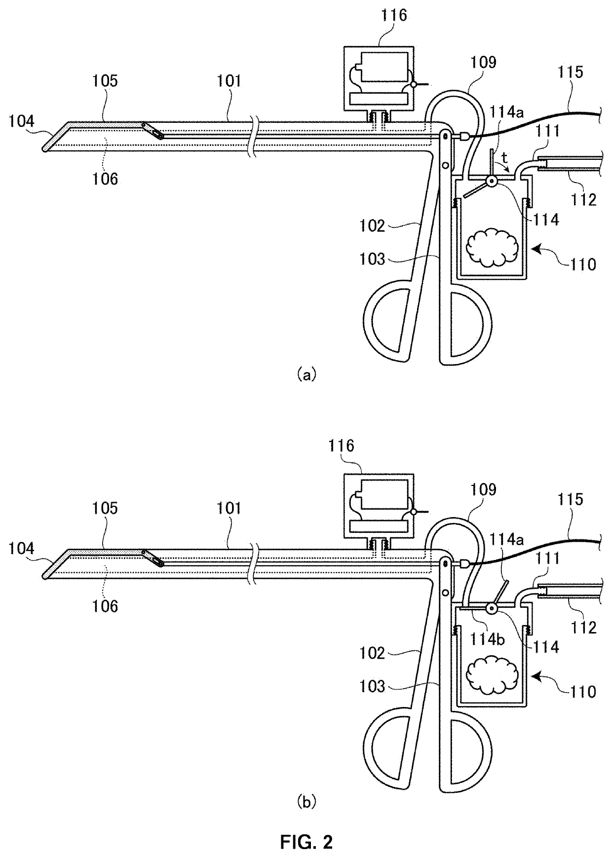
[0037]FIG. 1 is a schematic cross section showing a whole structure of a suction forceps 100 for endoscopic surgery according to this embodiment; FIG. 2 is a diagram showing suction operation in use of the suction forceps 100 for endoscopic surgery; FIG. 3 is a partly enlarged view showing a structure of a suction port 104 formed on a one end side of the suction forceps 100 for endoscopic surgery.

[0038]As shown in FIG. 1, the suction forceps 100 for endoscopic surgery according to this embodiment includes a body section 101 formed in a rod shape having a hollow section 106, a first control handle section 102 formed to extend in substantially a vertical direction from an end of the body section 101 in a lengthwise direction with a finger insertion portion 102a to insert an index finger of a surgeon, a second control handle section 103 arranged pivotally around a pivot portion 102b formed at the first control handle section 102 with a finger insertion portion 103a to insert a thumb of...

second embodiment

[0060]In a second embodiment, a structure having a suction stopping mechanism for stopping the suction at the suction port at the he suction forceps for endoscopic surgery of this invention, is described. FIG. 10 is illustration showing a structure on a tip side of a body section of a suction forceps 700 for endoscopic surgery according to a second embodiment; FIG. 11 is illustration showing a suction stopping mechanism 800 according to the second embodiment; FIG. 12 is illustration showing operation states of the suction stopping mechanism 800 according to the second embodiment; FIG. 13 is illustration showing another structure on the tip side of the body section of a suction forceps for endoscopic surgery according to the second embodiment; FIG. 14 is illustration showing yet another structure on the tip side of the body section of a suction forceps for endoscopic surgery according to the second embodiment. FIG. 15 is illustration showing a conventional suction pipe structure.

[006...


PUM


Abstract

To provide suction forceps for endoscopic surgery which are capable of quickly aspirating a fluid such as blood or another body fluid without requiring reinsertion of a dedicated aspiration tube even when there is leakage of blood or another body fluid during surgery, and consequently, also make it possible to prevent the duration of surgery from lengthening. Thus, suction forceps for endoscopic surgery are provided which are equipped with: a hollow section formed in a body section; a gripping part which manages tissue during surgery, and is formed at the tip end of the body section on one side thereof; and a suction port which is formed so as to be connected to the hollow section, and aspirates body fluid that has leaked from the tissue or blood that was effused during the surgery.

Description

FIELD OF THE INVENTION[0001]This invention relates to a suction forceps for endoscopic surgery having a suction function employed during surgery in use of an endoscope.BACKGROUND OF RELATED ART[0002]In endoscopic surgery using such as, e.g., laparoscope, and thoracoscope, conventionally, a scope, a forceps, an electric scalpel, and the like are inserted through a port (trocar) attached to such as, e.g., an abdominal wall or a chest wall, for surgical treatments such as, excision, hemostasis, suture in the coelom.[0003]For example, forceps of various types, having a gripping part at a tip of the tool for gripping targeted tissues or suture needles, have been known (see, e.g., Patent Document No. 1), but no forceps has been known in which a suction port is formed in the gripping part for suctioning liquid such as blood effused and body liquid leaking out of the tissues during surgery.PRIOR ART DOCUMENTS[0004]Patent Document No. 1: Japanese Patent Application Publication (A1) 2010-36,0...

Claims


Application Information

Patent Timeline
IPC IPC(8): A61B17/22A61B17/29A61B1/06A61B18/14
CPCA61B2017/22079A61B18/1445A61B1/0676A61B2218/007A61B17/22031A61B2217/005A61B2017/2947A61B17/29A61B2018/00589A61B90/30A61B18/16A61B2017/2926A61B2090/306A61M1/76A61M1/74A61M1/84
Inventor SAKURAZAWA, NOBUYUKI
Owner SAKURAZAWA NOBUYUKI
Learn More