
Dividing method for working region of self-moving device, dividing apparatus, and electronic device

a self-moving device and working region technology, applied in the direction of vehicle position/course/altitude control, process and machine control, instruments, etc., can solve the problems of safety problems, obstacle in the working area, adversely affecting the appearance of the lawn, etc., to improve the positioning precision of the self-moving device

Inactive Publication Date: 2019-11-14
POSITEC POWER TOOLS (SUZHOU) CO LTD
View PDF0 Cites 16 Cited by
  • Summary
  • Abstract
  • Description
  • Claims
  • Application Information

AI Technical Summary

Benefits of technology

The patent text discusses the problem of autonomous lawn mowers deviating from their expected path due to relatively large areas and small navigation positioning errors. The text proposes a solution to improve working precision by selecting the direction in which the mower enters a shaded region to shorten the duration it remains in the shaded region. This reduces the deviation from the expected path and improves the accuracy of the mower's positioning.

Problems solved by technology

When the autonomous lawn mower leaves the working region, a safety problem may occur.
In addition, an obstacle may exist in the working region.
Such a method requires complex arrangement of a boundary line and adversely affects the look of a lawn.
Another technical problem that follows is how to set more appropriately divided regions according to a feature of a working region, so that the autonomous lawn mower can safely and efficiently cover the working region.
However, because a lawn on which an autonomous lawn mower works usually has a relatively large area, a relatively small navigation positioning error may result in a relatively large deviation from an expected path.
Therefore, how to reduce a walking deviation of an autonomous lawn mower to improve working precision is a problem that urgently needs to be resolved in autonomous lawn mower technologies.
Buildings and obstacles usually exist in a working region of an autonomous lawn mower.
Satellite navigation signals usually tend to be blocked by the buildings, the obstacles, and the like and become weaker consequently.
For example, an autonomous lawn mower may fail to be located precisely when working in a shaded region due to weak GPS signals.

Method used


Image

  • Dividing method for working region of self-moving device, dividing apparatus, and electronic device
  • Dividing method for working region of self-moving device, dividing apparatus, and electronic device
  • Dividing method for working region of self-moving device, dividing apparatus, and electronic device

Examples


first embodiment

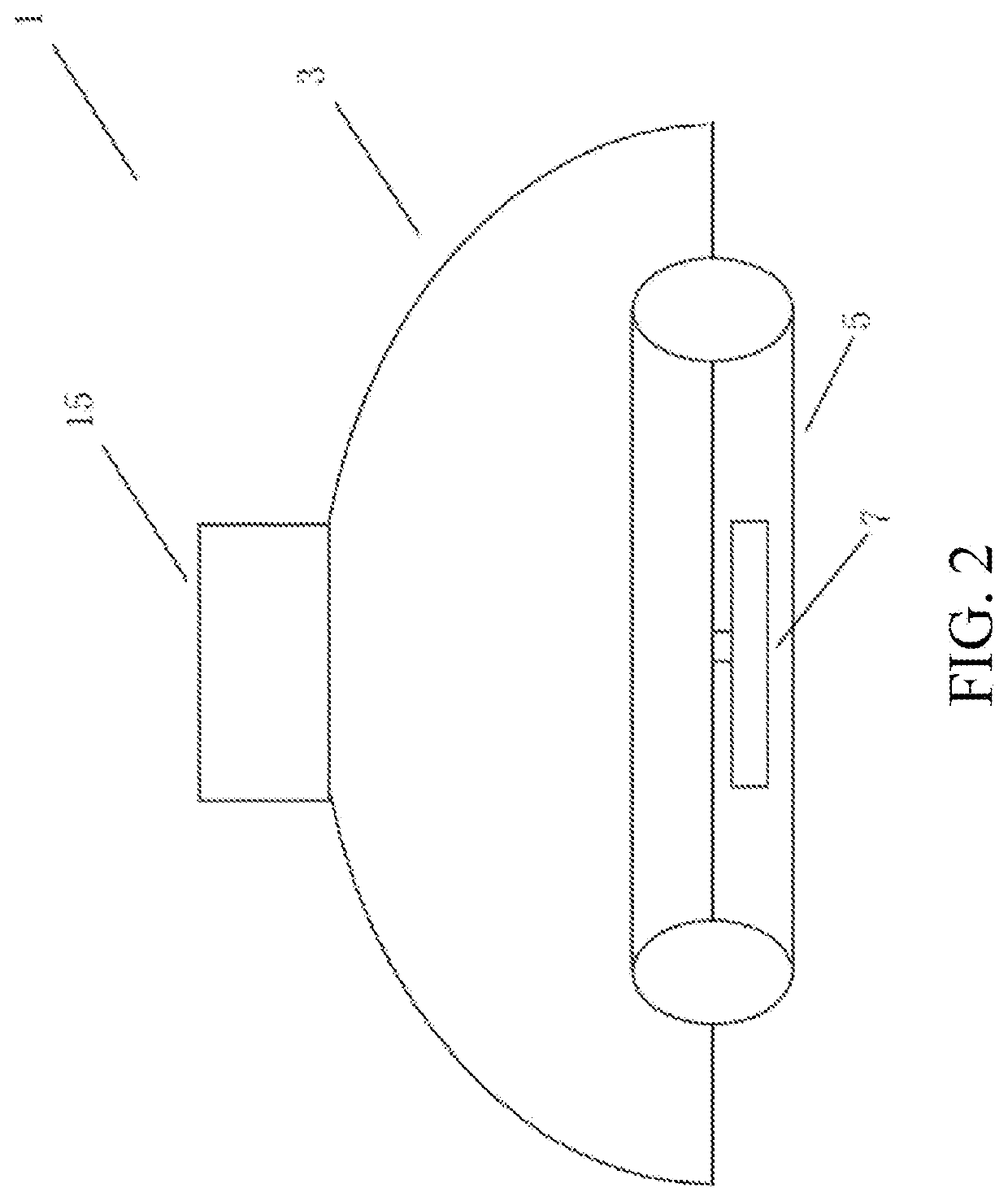
[0147]FIG. 1 is a schematic diagram of an autonomous working system 100 according to the present invention. The autonomous working system includes a self-moving device. In this embodiment, the self-moving device is an autonomous lawn mower 1. In another embodiment, the self-moving device may be alternatively an unattended device such as an autonomous cleaning device, an autonomous irrigation device, an autonomous snowplow, and the like. The autonomous working system 100 further includes a charging station 2 configured to charge the autonomous lawn mower 1. In this embodiment, the autonomous working system 100 includes a navigation module configured to output a current position of the autonomous lawn mower. Specifically, the navigation module includes a base station 17 and a mobile station 15.

[0148]As shown in FIG. 1, the autonomous working system is configured to work within a predetermined working region. In this embodiment, the working region includes at least two separate sub-wor...

second embodiment

[0155]In the present invention, to record the map, the mobile station is installed at the housing of the autonomous lawn mower, and the user uses an intelligent terminal device such as a mobile phone and a tablet to remotely control the autonomous lawn mower to move. Similarly, the step of recording the map includes recording the boundary of the working region, an obstacle in the working region, a passage connecting sub-regions or the like. In this embodiment, in the process of recording the map, an inertial navigation apparatus may be turned on. The reason is that the mobile station is installed at the housing of the autonomous lawn mower, and the mobile station moves relatively stably. In this embodiment, in the process of recording the map, the task execution module of the autonomous lawn mower is kept off.

third embodiment

[0156]In the present invention, the autonomous lawn mower includes a pushing rod, detachably installed at the housing of the autonomous lawn mower. To record the map, the mobile station is installed at the housing of the autonomous lawn mower, the pushing rod is installed at the housing of the autonomous lawn mower, and the user operates the pushing rod to push the autonomous lawn mower to move, to record the boundary of the working region, an obstacle, a passage or the like. Similarly, the task execution module of the autonomous lawn mower is kept off.


PUM


Abstract

The present invention relates to a moving method of a self-moving device, including: presetting a preset movement path of a self-moving device; enabling the self-moving device to move along the preset movement path; and checking whether a moving direction of the self-moving device deviates from the preset movement path, and when the moving direction deviates from the preset movement path, calibrating the moving direction of the self-moving device to enable the self-moving device to move along the preset movement path, wherein, the preset movement path including several first path segments, the first path segment being divided into several sub-path segments, and an end point of the sub-path segment being referred to as a node; and the calibrating the moving direction of the self-moving device includes: calibrating the moving direction of the self-moving device by using the node as a target point.

Description

BACKGROUNDTechnical Field[0001]Embodiments of the present invention relates to self-moving devices, and in particular, to a dividing method for a working region of a self-moving device, a dividing apparatus, and an electronic device.Related Art[0002]An autonomous working system such as an autonomous lawn mower system can autonomously complete a lawn maintenance task or the like, and becomes increasingly popular among consumers. In the autonomous working system, a self-moving device such as an autonomous lawn mower is restricted to move inside a working region. When the autonomous lawn mower leaves the working region, a safety problem may occur. In addition, an obstacle may exist in the working region. The obstacle includes a pit, a flowering shrub, and the like. The autonomous lawn mower should avoid the obstacle in the working region during working to prevent accidents such as falling or trapping. To ensure the safety of the autonomous working system and improve the working efficie...

Claims


Application Information

Patent Timeline
IPC IPC(8): G05D1/00G06F16/29G05D1/02G01S19/41G01S19/47
CPCG05B13/0265G05D1/0278G01S19/41G01S19/47G05D1/0212G06F16/29G05D2201/0208G05D1/0088G05D1/0255G05D1/0257G05D1/024G05D1/0246G05D1/0259G05D1/0223G05D1/0276G05D1/0268G01C25/00G05B23/02G06Q10/04G06F16/00G01S19/49G01S19/48G01S19/485G01S19/35G01S19/071G01S19/396A01D34/008G05D1/0214G05D1/0225A01D2101/00
Inventor ZHOU, CHANGTAN, YIYUNLIU, FANGSHISHAO, YONG
Owner POSITEC POWER TOOLS (SUZHOU) CO LTD
Learn More