Oil tank system

Active Publication Date: 2019-11-07
ROLLS ROYCE PLC
View PDF3 Cites 2 Cited by
  • Summary
  • Abstract
  • Description
  • Claims
  • Application Information

AI Technical Summary

Benefits of technology

The patent describes a way to improve the ability of a surface to stick to oil, such as aviation oil. This is done by creating micro-voids, channels, ridges, or protrusions on the surface of the waisted section where the oil can adhere to. The size and shape of these features are designed to enhance the adhesion with a particular type of oil. Additionally, the patent also mentions the use of baffles to reduce swirling of the oil within the tank. Overall, these features improve the oil tank's ability to hold oil and prevent it from leaking or splashing during use.

Problems solved by technology

Scavenge pumps are used to extract the oil, but this often results in a mixture of air and oil, being extracted by the scavenge pump and being fed to the oil tank system.
Where this larger capacity results in a significantly extended vertical extent of the oil tank, it has been noted that oil leaving the de-aerator and being deposited in the oil tank may fall a substantial distance from the de-aerator, depending on the oil level within the oil tank, resulting in agitation of the oil surface, oil splash, partial reaeration of the oil, and an unrepresentative indicated oil level, which is undesirable.

Method used


Image

  • Oil tank system
  • Oil tank system
  • Oil tank system

Examples


Embodiment Construction

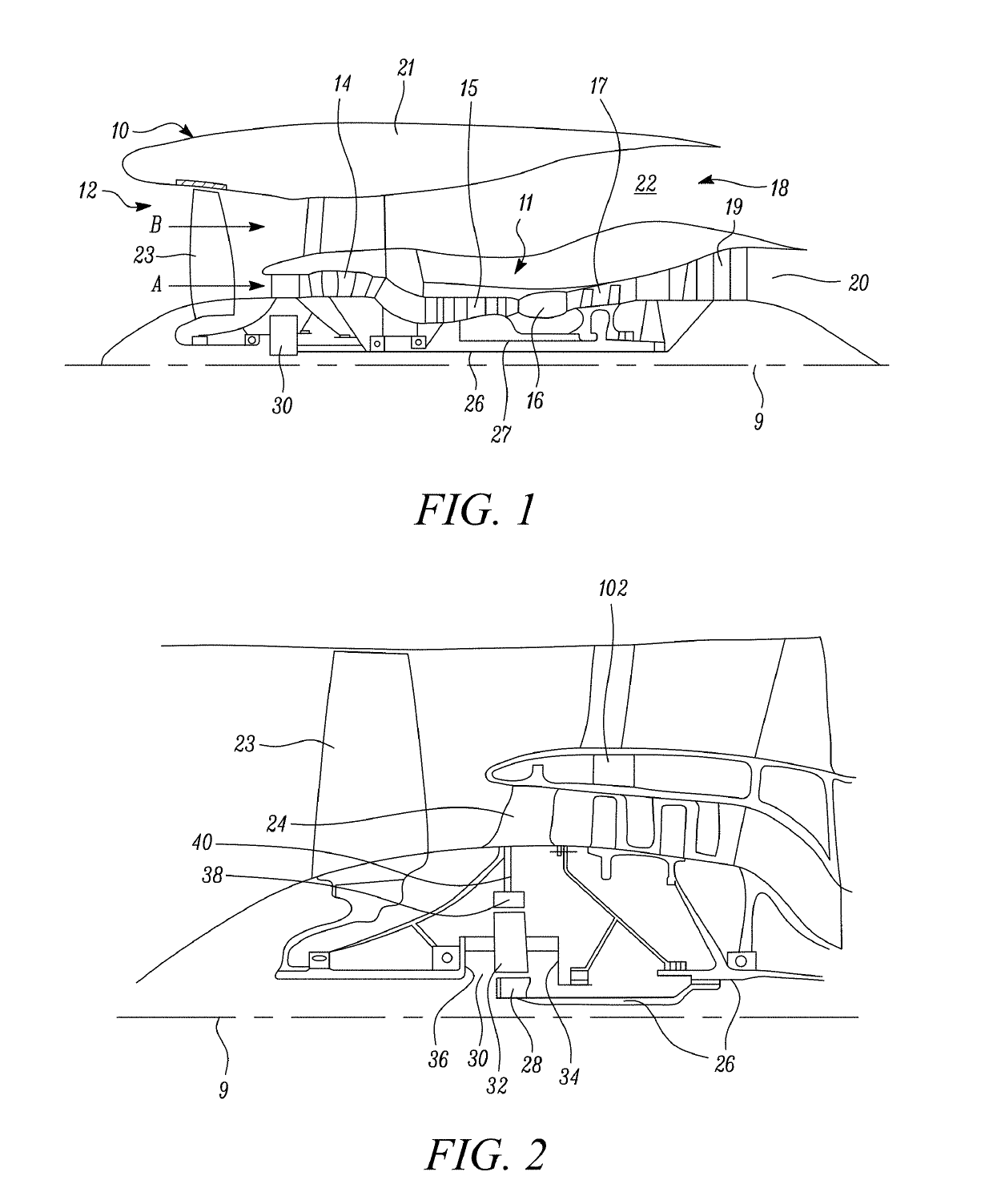
[0047]As noted elsewhere herein, the present disclosure relates to a gas turbine engine. Such a gas turbine engine may comprise an engine core comprising a turbine, a combustor, a compressor, and a core shaft connecting the turbine to the compressor. Such a gas turbine engine may comprise a fan (having fan blades) located upstream of the engine core.

[0048]Arrangements of the present disclosure may be particularly, although not exclusively, beneficial for fans that are driven via a gearbox. Accordingly, the gas turbine engine may comprise a gearbox that receives an input from the core shaft and outputs drive to the fan so as to drive the fan at a lower rotational speed than the core shaft. The input to the gearbox may be directly from the core shaft, or indirectly from the core shaft, for example via a spur shaft and / or gear. The core shaft may rigidly connect the turbine and the compressor, such that the turbine and compressor rotate at the same speed (with the fan rotating at a low...


PUM

PropertyMeasurementUnit
Speedaaaaaaaaaa

Abstract

An oil tank system (100) for a gas turbine engine is provided. The oil tank system (100) includes an oil tank (102) having an upper tank portion (112) and a lower tank portion (114), a waisted section (118) being provided between the upper tank portion (112) and the lower tank portion (114). Oil is received by a de-aerator (104) of the system (100) which supplies de-aerated oil to the upper tank portion (112). The waisted section (118) includes an upper face (119) configured to catch oil drips from above the waisted section (118) and to guide oil to a lower face (121) of the waisted section (118).

Description

CROSS-REFERENCE TO RELATED APPLICATIONS[0001]This specification is based upon and claims the benefit of priority from United Kingdom patent application GB 1807265.2 filed on May 3rd 2018, the entire contents of which are incorporated herein by reference.BACKGROUNDField of the Disclosure[0002]The present disclosure relates to an oil tank system for a gas turbine engine, and more particularly but not necessarily exclusively for a gas turbine engine comprising a gearbox. The present disclosure also relates to a gas turbine engine including an oil tank system and an aircraft including a gas turbine engine including an oil tank system.Description of the Related Art[0003]Oil tank systems, particularly those in aircraft, are used to store oil from a part of an oil system such that the oil may be recirculated throughout the system. Scavenge pumps are used to extract the oil, but this often results in a mixture of air and oil, being extracted by the scavenge pump and being fed to the oil tan...

Claims


Application Information

Patent Timeline
IPC IPC(8): F01D25/18F02K3/06F01M11/00F01M11/08B64D27/10B01D19/00
CPCF02K3/06F05D2260/608F01M2011/0033B01D19/0057F05D2260/98B64D27/10F05D2220/323F01M11/0004F01D25/18F02C7/36F01M2250/60F05D2260/40311F01M11/08B64D37/02B64D37/06F02C7/06F02C7/32F05D2250/292F16N19/00F16N2210/02F16N39/002F01M2011/0037
Inventor REID, MARK P.
Owner ROLLS ROYCE PLC
Why Eureka
Try Eureka