Method for calibrating ultrasonic transducers and system for carrying out the method

Active Publication Date: 2019-10-24
ROBERT BOSCH GMBH
View PDF0 Cites 0 Cited by
  • Summary
  • Abstract
  • Description
  • Claims
  • Application Information

AI Technical Summary

Benefits of technology

The present invention provides a method for calibrating ultrasonic transducers in a way that improves measurement accuracy. This is by detecting and compensating for production and operation-induced differences between the individual transducers. This allows for increased accuracy when measuring distances to objects, even at close distances. The calibration takes place simultaneously with object measurement, so a separate calibration mode is not necessary. The correction value is ascertained during each transmission cycle of the ultrasonic transducer operated in the transmission mode, in order to compensate for fluctuating temperatures and ensures a particularly precise distance measurement.

Problems solved by technology

It is essential that the described method is utilized only for detecting the correct installation sites of the ultrasonic transducers in the bumper, but not for being able to detect and correct production- and / or operation-induced measuring inaccuracies of the ultrasonic transducers, which occur, in particular, due to a different transient response of the ultrasonic transducers or as a function of the operating temperature of the ultrasonic transducers.
If multiple objects are located in the detection range of the ultrasonic transducers, however, ambiguities occur, since the echo assignment of the ultrasonic transducers operated in the receiving mode to the individual objects is not known.
If typical standard transducers are to be utilized instead of a so-called ultrasonic array which encompasses a plurality of transducers in a small space, a reduction of the distances between the ultrasonic transducers, which results in a reduction of the ambiguity in the detection of multiple objects, simultaneously results in a greater inaccuracy with respect to the lateral position of the object, however.

Method used


Image

  • Method for calibrating ultrasonic transducers and system for carrying out the method
  • Method for calibrating ultrasonic transducers and system for carrying out the method
  • Method for calibrating ultrasonic transducers and system for carrying out the method

Examples


Embodiment Construction

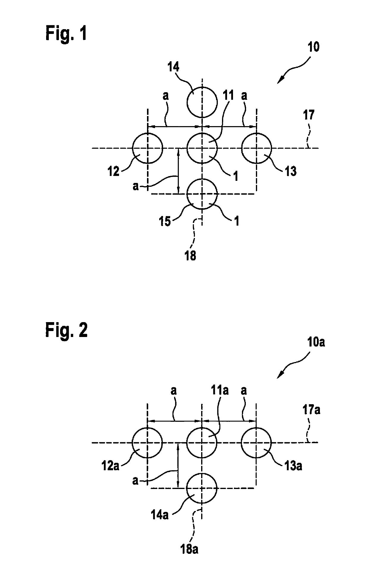
[0020]FIG. 1 shows a first system 10 made up of five ultrasonic transducers 11 through 15, of the type which are situated, in particular, in the area of a bumper of a motor vehicle and are utilized for measuring the distance to an object. Ultrasonic transducers 11 through 15 are designed according to the related art, reference being made, by way of example, with respect to their design and mode of operation, to German Patent Application No. DE 10 2005 052 633 A1, which, in this regard, is expressly incorporated herein by reference in its entirety. Moreover, ultrasonic transducers 11 through 15 are coupled via a cable harness of the motor vehicle to a control unit (not represented).

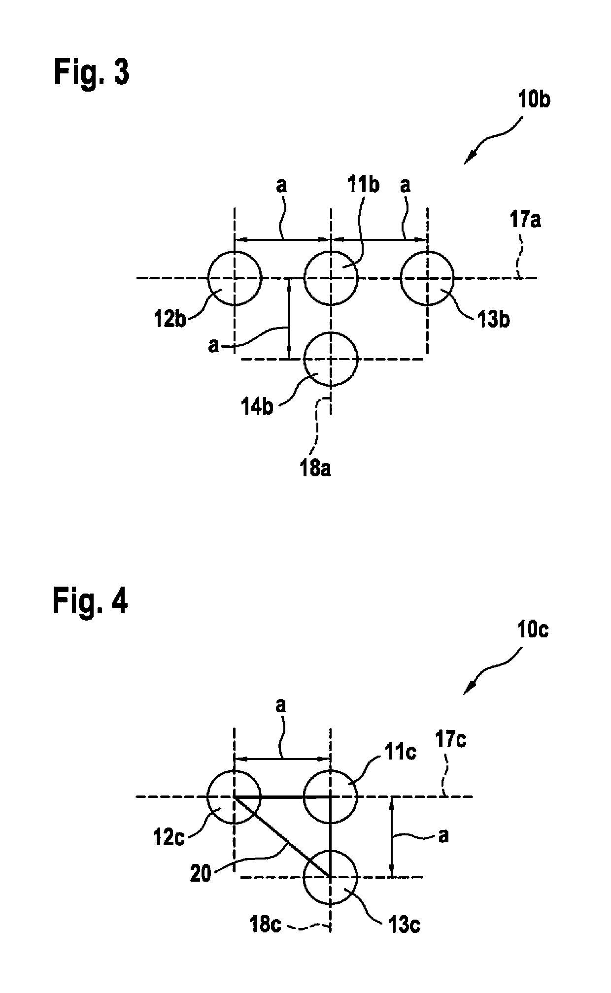
[0021]Circular or cup-shaped, oscillatory diaphragm elements 1, which are represented in FIGS. 1 through 5, of the five ultrasonic transducers 11 through 15 are situated in the manner of a cross on two axes 17, 18 situated perpendicularly to one another, by way of example. Centrally situated ultrasonic tra...


PUM


Abstract

A method for calibrating ultrasonic transducers, the ultrasonic transducers being situated at known distances or at known ratios of the distances from one another, preferably in a bumper of a motor vehicle, and one of the ultrasonic transducers is operated in a transmission mode, and at least one other ultrasonic transducer is operated in a receiving mode.

Description

FIELD[0001]The present invention relates to a method for calibrating ultrasonic transducers. Moreover, the present invention relates to a system for carrying out the method.BACKGROUND INFORMATION[0002]A method for calibrating ultrasonic transducers is described in German Patent No. DE 10 2014 224 509 B3. The described method is utilized for detecting the correct installation sites of ultrasonic transducers in the bumper of a motor vehicle. This means, whether an ultrasonic transducer intended for a certain installation site in a bumper is also actually installed at this site. For this purpose, the relevant ultrasonic transducer is operated in a transmission mode and the signal propagation time to an adjacent ultrasonic transducer is recorded. The recorded actual signal propagation time is compared to a setpoint signal propagation time which is to be expected in the case of a correct placement of the ultrasonic transducer which is situated at a certain distance from the ultrasonic tr...

Claims


Application Information

Patent Timeline
IPC IPC(8): G01S7/52G01S15/93G01S15/08G01S7/521G01S15/931
CPCG01S15/08G01S7/52004G01S7/521G01S2015/938G01S15/931
Inventor SCHUMANN, MICHAEL
Owner ROBERT BOSCH GMBH
Why Eureka
Try Eureka