Stress relief for additive layer manufacturing

Inactive Publication Date: 2019-10-24
ROLLS ROYCE PLC
View PDF0 Cites 0 Cited by
  • Summary
  • Abstract
  • Description
  • Claims
  • Application Information

AI Technical Summary

Benefits of technology

The use of a stress relieving layer between the component and the substrate can accommodate differential stresses during fabrication and post-fabrication processing steps. This helps in reducing or eliminating distortion of the component and substrate, as well as ensuring reduced cracking and deformation. The stress-relieving layer has a different shear stiffness in two directions, allowing for more strain to be relieved in the direction aligned with the longer dimension of the component. A lower density stress-relieving layer can also help thermally isolate the component from the substrate. The stress-relieving layer can be formed by partially fusing the layers and has a porous structure with open or closed pores. This method is particularly useful for alloys used in high temperature environments.

Problems solved by technology

For other materials such as metals, fabrication options may be more limited, especially if the melting point of the metal is high or if the metal is reactive.
Ceramic components may also be manufactured by ALM but, due to their high melting point, high stiffness and generally low thermal conductivity, it is typically not possible to directly generate an ALM part from a powder precursor.
A problem with forming components via ALM, particularly for metallic components, is that directly fusing one layer on top of previous layers can generate high residual stresses within the component.
This may cause distortion in the finished component, resulting in the need for post-fabrication machining.
If the substrate on which the component is built is of sufficient thickness and strength, distortion of the component may be reduced or eliminated, but this will lead to higher residual stresses in the component.
Typically the substrate may be a different material to the component being manufactured, which can result in a thermal mismatch leading to higher residual stresses.

Method used


Image

  • Stress relief for additive layer manufacturing
  • Stress relief for additive layer manufacturing
  • Stress relief for additive layer manufacturing

Examples


Embodiment Construction

[0035]It will be understood that the invention is not limited to the embodiments above-described and various modifications and improvements can be made without departing from the concepts described herein. Except where mutually exclusive, any of the features may be employed separately or in combination with any other features and the disclosure extends to and includes all combinations and sub-combinations of one or more features described herein.

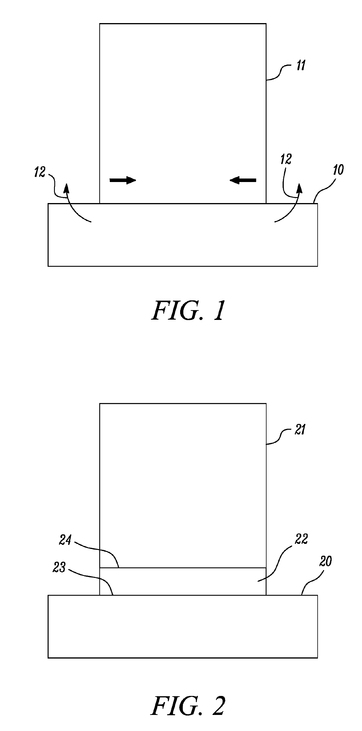
[0036]FIG. 1 illustrates an example component 11 fabricated on a substrate 10 by ALM. The component 11 may be made up of a plurality of layers formed over one another by fusing a powder feedstock with a laser. As each successive layer is fused, an increasing stress is built up between the substrate 10 and the component 11 due to thermal contraction as the layers cool down from being fused at high temperatures. This may eventually cause the substrate 10 to deform in the general way indicated by arrows 12, which may result in distortion of the...


PUM

PropertyMeasurementUnit
Structureaaaaaaaaaa
Densityaaaaaaaaaa
Stiffnessaaaaaaaaaa

Abstract

The present disclosure relates to techniques for stress relief in additive layer manufacturing (ALM). Example embodiments include a method for additive layer manufacturing of a metallic component, comprising the steps of: providing a substrate (20); depositing a first layer (22) of material on the substrate (20); depositing a plurality of second layers of material on the first layer (22) to form the metallic component (21), wherein the first layer (22) forms a stress relieving layer between the plurality of second layers and the substrate (20), the stress relieving layer having a lower shear stiffness compared to the metallic component (21).

Description

CROSS-REFERENCE TO RELATED APPLICATIONS[0001]This specification is based upon and claims the benefit of priority from United Kingdom patent application Number GB 1806369.3 filed on Apr. 19, 2018, the entire contents of which are incorporated herein by reference.BACKGROUNDTechnical Field[0002]The present disclosure relates to techniques for stress relief in additive layer manufacturing (ALM), in particular relating to fabrication of metallic components by ALM.Description of the Related Art[0003]ALM is a technique that allows for articles to be manufactured of arbitrary shape without moulding or machining. Articles made via ALM are formed layer by layer, with each additional layer being fused to previous layers. The technique can be applied to a wide range of materials including polymers, metals and ceramics, each with particular requirements for providing the required feedstock, typically in the form of a particulate material, and power to cause fusion of the layers.[0004]For polymer...

Claims


Application Information

Patent Timeline
IPC IPC(8): B22F3/105
CPCB33Y70/00B33Y80/00B22F2003/1058B33Y10/00B22F2203/05B22F3/1055B22F2998/10B33Y40/00B22F2303/405Y02P10/25B22F10/66B22F10/47B22F10/28B22F10/64
Inventor STAPLETON, DAVIDO'BRIEN, STUART B.
Owner ROLLS ROYCE PLC
Why Eureka
Try Eureka