
LOW NOx BURNER AND FLOW MOMENTUM ENHANCING DEVICE

a technology of flow momentum and burner, which is applied in the direction of burners, combustion types, combustion processes, etc., can solve the problems of not being able to break all of the nsub>2/sub>bonds, and achieve the effects of reducing nox emissions, increasing flow momentum, and lowering the peak flame temperature of the burner

Active Publication Date: 2019-10-10
ZEECO
View PDF5 Cites 2 Cited by
  • Summary
  • Abstract
  • Description
  • Claims
  • Application Information

AI Technical Summary

Benefits of technology

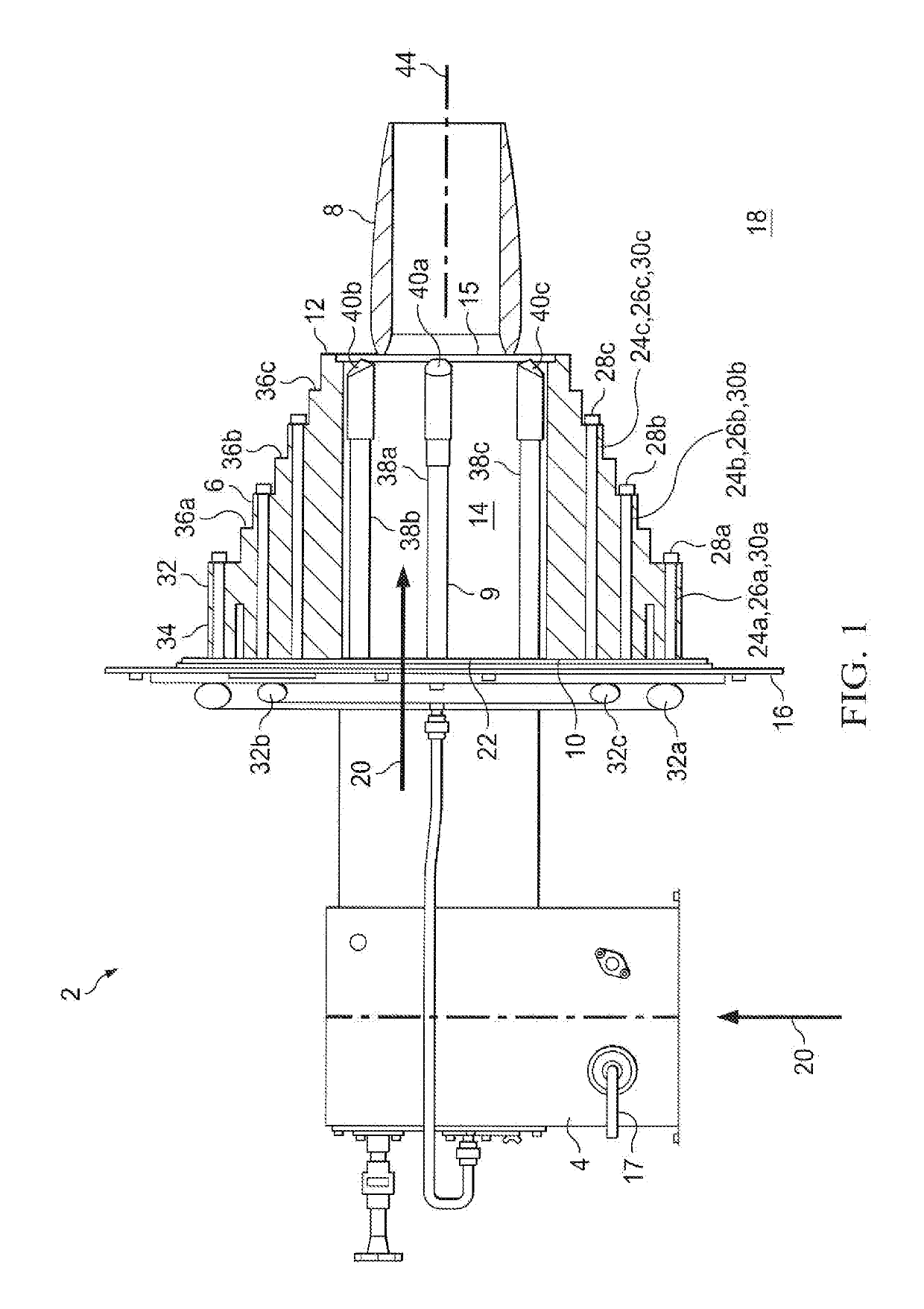
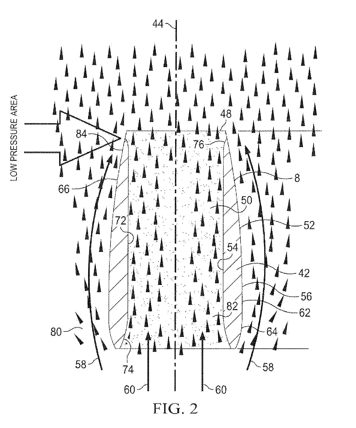
The inventive device and method described in this patent are designed to decrease NOx emissions and reduce harmful air pollutants from burners. It achieves this by increasing the flow momentum of the combustion air and creating a low pressure region that pulls in more inert products of combustion present in the system. This decreases the peak flame temperature of the burner and increases the amount of recirculated flue gas, which reduces NOx emissions and other hazardous pollutants. The device also enhances the mixing of the recirculated flue gas with the burner combustion mixture, decreasing flame length, CO emissions, and other emissions. Additionally, the method reduces NOx emissions from the burner by up to 60% and achieves a more efficient mixing of the recirculated flue gas and the burner combustion mixture.

Problems solved by technology

However, when the fuel is burned under less than ideal conditions, e.g., at a high flame temperature, nitrogen present in the combustion air reacts with oxygen to produce nitrogen oxides (NOx).
Typically, the temperature of combustion is not great enough to break all of the N2 bonds.

Method used


Image

  • LOW NOx BURNER AND FLOW MOMENTUM ENHANCING DEVICE
  • LOW NOx BURNER AND FLOW MOMENTUM ENHANCING DEVICE
  • LOW NOx BURNER AND FLOW MOMENTUM ENHANCING DEVICE

Examples


embodiment 160

[0075]Another alternative embodiment 160 of the inventive burner apparatus is illustrated in FIG. 12. The inventive burner apparatus 160 is identical to the burner apparatus 2 illustrated in FIG. 12, and can also be identical to any of the alternative configurations or embodiments of the inventive burner 2 illustrated in FIGS. 4, 5 and 9, except that (a) the forward portion 162 of the burner wall 164 of the burner 160 has a sloped exterior which converges inwardly toward the forward longitudinal end 166 of the burner wall 164 and (b) the burner apparatus 160 is illustrated as having only a single series of external fuel ejectors 168 which surround the burner wall 164.

embodiment 170

[0076]Another alternative embodiment 170 of the inventive burner apparatus is illustrated in FIG. 13. The inventive burner apparatus 170 is identical to the inventive burner 160 except that, in the inventive burner 170, a plurality of lateral flue gas passageways 172 extend through the burner wall 174 to the combustion air passageway 176 of the burner wall 174 for aspirating internal products of combustion from the combustion chamber 40 into the combustion air stream flowing though the combustion air passageway 176.

embodiment 180

[0077]Another alternative embodiment 180 of the inventive burner apparatus is illustrated in FIG. 14. The inventive burner apparatus 180 is identical to the inventive burner 160 except that the inventive burner apparatus 180 further comprises a fuel riser 182 which extends through the combustion air passageway 184 of the burner wall 186 to a primary fuel discharge tip 188. The primary fuel discharge tip 188 can be located in, at the forward longitudinal end 48 of, or forwardly of the interior passageway 50 of the inventive flow momentum enhancing device 8.


PUM


Abstract

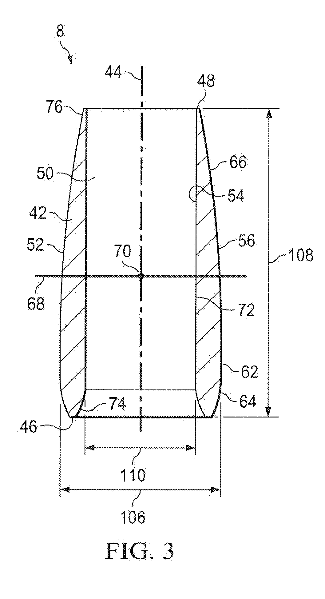
A flow momentum enhancing device having an airfoil shape is used in a new or refurbished burner to increase the momentum of the burner combustion air stream and create a reduced pressure region which pulls inert products of combustion into the combustion process. The inert products of combustion mix with the burner air and / or fuel streams to lower the peak flame temperature of the burner and provide reduced NOx production.

Description

FIELD OF THE INVENTION[0001]The present invention relates to burner apparatuses and methods for reducing NOx emissions from heaters, boilers, incinerators, other fired heating systems, flares, and other combustion systems of the type used in refineries, power plants, and chemical plants, on offshore platforms, and in other industrial services and facilities.BACKGROUND OF THE INVENTION[0002]A continuing need exists for burners, burner combustion methods, add-ons for new and refurbished burners, and burner refurbishing methods which will significantly reduce NOx emissions from fired heaters, boilers, incinerators, flares and other combustion systems used in industrial processes. The improved new and refurbished burners will also preferably provide flame lengths, turndown ratios, and stability levels which are at least as good as or better than those provided by the current burner designs.[0003]For burners which are used in industrial applications, if the burner fuel is thoroughly mixe...

Claims


Application Information

Patent Timeline
IPC IPC(8): F23D14/02F23D14/70
CPCF23D14/02F23D14/70F23D14/22F23D11/404F23D2900/11401F23D2900/14641F23M5/025
Inventor ZINK, DARTON J.ISAACS, REX K.PETERSEN, JOHNLITTLE, CODYKIRK, TIM
Owner ZEECO
Learn More