A method and system for controlling the rotational speed of an expander in a waste heat recovery system

a waste heat recovery and expander technology, applied in the direction of mechanical equipment, machines/engines, transportation and packaging, etc., can solve the problems of reducing the amount of heat that can be handled in the waste heat recovery system, limiting the heat that can be handled in the system, and affecting the operation of the system. , to achieve the effect of reducing the pressure of the working fluid and increasing the rotational speed of the expander

Inactive Publication Date: 2019-10-10
SCANIA CV AB
View PDF5 Cites 0 Cited by
  • Summary
  • Abstract
  • Description
  • Claims
  • Application Information

AI Technical Summary

Benefits of technology

[0008]An object of the present invention is to achieve an advantageous method for controlling a waste heat recovery system, which increases the lifetime of the system.
[0010]A further object of the invention is to achieve an advantageous waste heat recovery system, which is adapted to be controlled such that the lifetime is increased.
[0017]The operating temperature of the waste heat recovery system is normally quite high. For ideal gases the pressure is directly proportional to the temperature and too high temperature of the working fluid may thus cause a too high pressure of the working fluid on the high pressure side of the waste heat recovery system where the working fluid is a vapour. The high pressure side of the waste heat recovery system is downstream of the pump and upstream of the expander. Too high pressure of the working fluid may damage the various components of the system. At too high pressure the working fluid may also shift to a liquid phase and this could damage the expander. The pressure of the working fluid can be decreased or increased by controlling the rotational speed of the expander. When the rotational speed of the expander is increased, the mass flow of the working fluid handled by the expander is increased and the pressure of the working fluid in the circuit upstream of the expander is thereby decreased. By determining the pressure of the working fluid upstream of the expander and controlling the rotational speed of the expander based on the determined pressure, too high pressure upstream of the expander can be avoided. Also, since the temperature of the working fluid is linked to the pressure and affects the working fluid and the components of the system, it is advantageous to control the rotational speed of the expander based on the determined temperature. This way, the energy recovery is optimized and the lifetime of the waste heat recovery system is increased.
[0023]According to an aspect of the invention the rotational speed of the expander is increased if there is a risk that the pressure of the working fluid will exceed the predetermined maximum pressure and / or that the difference between the temperature and the boiling point of the working fluid will become smaller than the predetermined minimum temperature difference. By increasing the rotational speed of the expander when there is a risk that the difference between the temperature and the boiling point of the working fluid will become smaller than the predetermined minimum temperature difference, the pressure of the working fluid is pre-emptively decreased and the damage of the waste heat recovery system is avoided while optimizing the energy recovery. Similarly, by increasing the rotational speed of the expander when there is a risk that the pressure will exceed the predetermined maximum pressure the pressure of the working fluid is decreased pre-emptively and damage of the waste heat recovery system is avoided while optimizing the energy recovery.

Problems solved by technology

This is specifically an issue for manufacturers of heavy vehicles, such as trucks and buses.
The temperature and pressure of the working fluid are limited by hardware constraints on the high pressure side, i.e. upstream of the expander.
The hardware constraints limit the amount of heat that can be handled in the waste heat recovery system.
Excessive heat may cause too high pressure of the working fluid upstream of the expander, which may damage the components of the system.
If the pressure is too high the working fluid may condensate which for example could damage the expander.
Such solution thus results in some exhaust gas energy being wasted.

Method used


Image

  • A method and system for controlling the rotational speed of an expander in a waste heat recovery system
  • A method and system for controlling the rotational speed of an expander in a waste heat recovery system
  • A method and system for controlling the rotational speed of an expander in a waste heat recovery system

Examples


Embodiment Construction

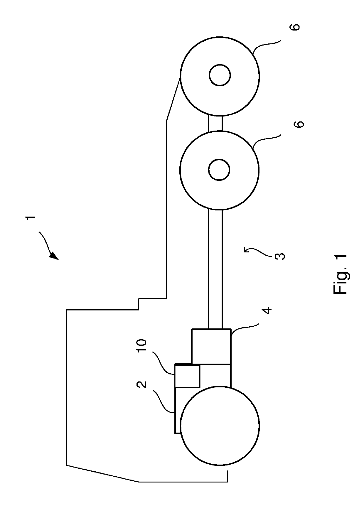
[0041]FIG. 1 schematically shows a side view of a vehicle 1 according to an embodiment of the invention. The vehicle 1 has a powertrain 3 comprising a combustion engine 2 and a gearbox 4 connected to the combustion engine 2 and the driving wheels 6 of the vehicle 1. The vehicle 1 further comprises a waste heat recovery system 10 associated with the powertrain 3. The vehicle 1 may be a heavy vehicle, e.g. a truck or a bus. The vehicle 1 may alternatively be a passenger car. The vehicle may be a hybrid vehicle comprising an electric machine (not shown) in addition to the combustion engine 2.

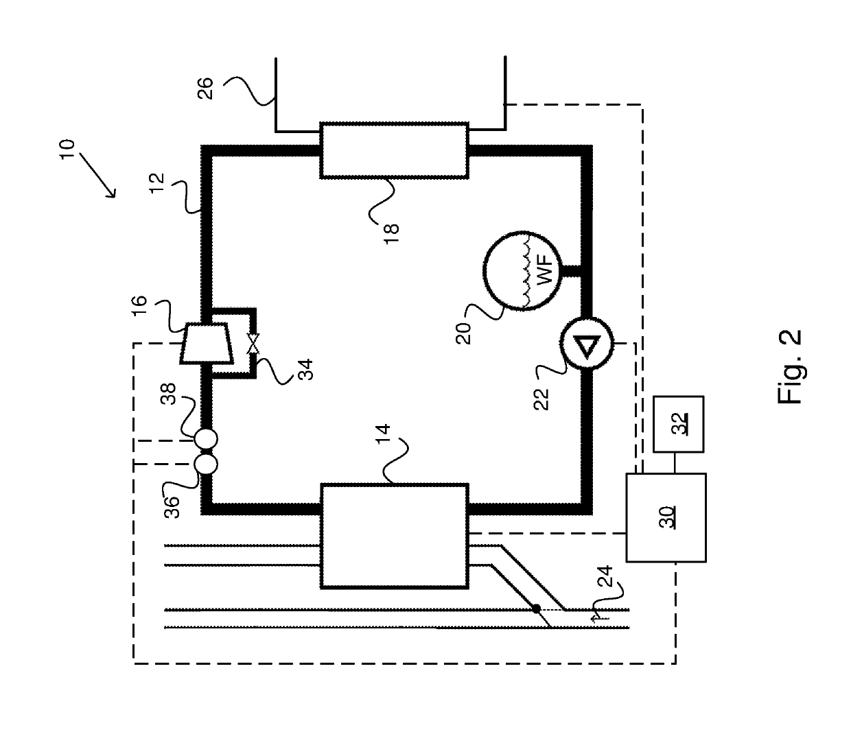
[0042]FIG. 2 schematically shows a waste heat recovery system 10 associated with a powertrain 3 of a vehicle 1 according to an embodiment of the invention. The vehicle 1 is suitably configured as described in FIG. 1. The waste heat recovery system 10 comprises a working fluid circuit 12; an evaporator 14; an expander 16; a condenser 18; a reservoir 20 for a working fluid WF and a pump 22 arranged t...


PUM


Abstract

The invention relates to a method, system, and computer program product for controlling a waste heat recovery system associated with a vehicle powertrain, the powertrain comprising a combustion engine and a gearbox connected to the combustion engine, the waste heat recovery system comprising a working fluid circuit; an evaporator; an expander; a condenser; a reservoir for a working fluid and a pump arranged to pump the working fluid through the circuit, wherein the evaporator is arranged for heat exchange between the working fluid and at least one heat source, wherein the waste heat recovery system further comprises a cooling circuit arranged in connection to the condenser, and wherein the expander is mechanically coupled to the powertrain. The method comprises the steps of determining the pressure and temperature of the working fluid upstream of the expander; and controlling the rotational speed of the expander based on the determined pressure and temperature.

Description

CROSS-REFERENCE TO RELATED APPLICATIONS[0001]This application is a national stage application (filed under 35 § U.S.C. 371) of PCT / SE2017 / 050484, filed May 12, 2017 of the same title, which, in turn, claims priority to Swedish Application No. 1651039-8 filed Jul. 12, 2016; the contents of each of which are hereby incorporated by reference.FIELD OF THE INVENTION[0002]The present invention relates to a method for controlling a waste heat recovery system, a waste heat recovery system, a vehicle comprising such a waste heat recovery system, a computer program and a computer program product according to the appended claims.BACKGROUND OF THE INVENTION[0003]Vehicle manufacturers are today striving to increase engine efficiency and reduce fuel consumption. This is specifically an issue for manufacturers of heavy vehicles, such as trucks and buses. In vehicles with combustion engines some of the energy from the fuel is dissipated as heat through the exhaust pipes and the engine cooling syste...

Claims


Application Information

Patent Timeline
Patent Type & Authority Applications(United States)
IPC IPC(8): F01K13/02F01K23/06F01K23/10F01P3/22F02G5/04B60K11/02
CPCB60K11/02F01K23/065F01K23/101F02G2260/00F02G5/04F01K13/02F01K27/02F01P3/2285F01N5/02F01K23/10F02G5/02F01K23/14F01K15/02Y02T10/12F01K23/06
Inventor JOHANSSON, BJÖRNHÖCKERDAL, ERIKTIMREN, THOMAS
Owner SCANIA CV AB
Why Eureka
Try Eureka