Antenna feed structure and base station antenna

a technology of antenna feed structure and antenna feed structure, which is applied in the field of mobile communications, can solve the problems of poor cross polarization ratio performance, difficult debugging, affecting the characteristics of antenna gain, communication coverage quality, etc., and achieves the optimization of the performance of a directional diagram, indirect grounding, and improved radiation performance.

Inactive Publication Date: 2019-09-19
PROSE TECH CO LTD
View PDF16 Cites 8 Cited by
  • Summary
  • Abstract
  • Description
  • Claims
  • Application Information

AI Technical Summary

Benefits of technology

[0007]An objective of the present invention is to overcome the defects of the prior art, and provide an antenna feed structure and a base station antenna, which are used to improve the performance of antenna radiation and increase a cross polarization ratio of the antenna.
[0009]Preferably, the position of the groove on the surface of the end of the antenna feed balun connected to the ground is adjustable. In the course of transmitting an excitation signal to a vibrator of the radiator, the current distribution of the antenna is changed by adjusting the position of the groove (i.e., a position of an indirectly grounded point of the antenna feed structure), to adjust the radiation performance, such that the performances of the antenna radiation, in particular a cross polarization ratio are greatly improved.
[0020]Compared with the prior art, the present invention has the advantages that indirect grounding of the antenna feed balun is realized by forming the groove at the surface of the end of the antenna feed balun connected to the ground (i.e., a surface connected to the ground, connected to the antenna feed board, of the radiating element) or additionally digging a hole on the basis of forming the groove. In addition, the current distribution of the antenna is changed by adjusting the position of the intermittently grounded point to optimize the performance of a directional diagram, thereby greatly improving the radiation performance, in particular the cross polarization ratio, facilitating an increase in an antenna gain, improving the base station coverage and optimizing the electrical characteristics of the antenna.

Problems solved by technology

In practical use and research experiments, we have found that the antenna with such an unintermittent grounding structure has a poor cross polarization ratio performance of the antenna radiation, and is difficult to debug, thereby affecting the characteristics of antenna gain, communication coverage quality and the like.

Method used


Image

  • Antenna feed structure and base station antenna
  • Antenna feed structure and base station antenna
  • Antenna feed structure and base station antenna

Examples


Embodiment Construction

[0031]The technical solution of the embodiments of the present invention will be clearly and completely described below with reference to the accompanying drawings.

[0032]The accompanying drawings may show one or more structural features in different viewing angles. In each of the accompanying drawings, solid lines may be used to show visible outlines or edges of structures, and dashed lines may be used to show invisible or hidden outlines or edges of the structures.

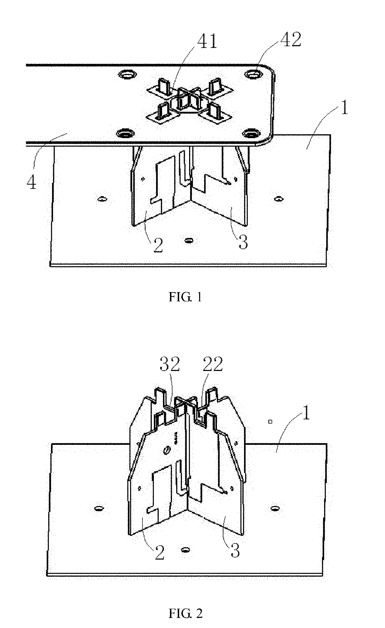
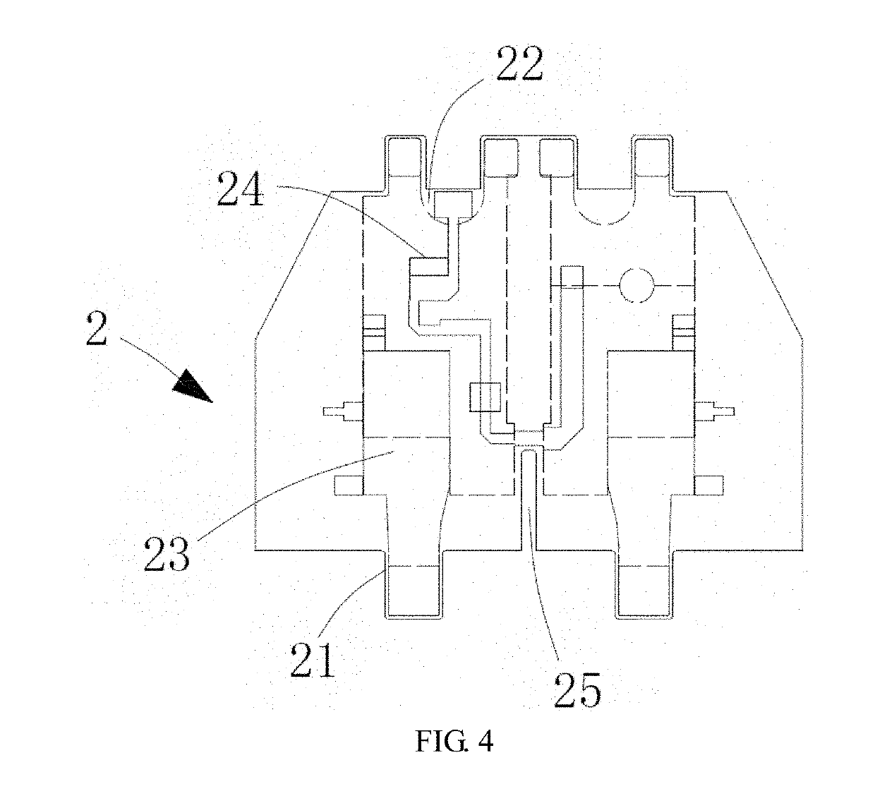
[0033]According to an antenna feed structure and a base station antenna disclosed by the present invention, the performances of antenna radiation can be improved, and the cross polarization ratio of the antenna is improved, facilitating an increase in an antenna gain, improving the base station coverage and optimizing the electrical characteristics of the antenna.

[0034]As shown in FIGS. 1 and 2, an antenna feed structure disclosed by an embodiment of the present invention comprises a radiator 1, an antenna feed balun, an ...


PUM


Abstract

The invention discloses an antenna feed structure and a base station antenna. The base station antenna comprises a plane reflector and at least one antenna feed structure installed thereat. The antenna feed structure comprises a radiator, an antenna feed balun and an antenna feed board. The antenna feed balun comprises one end connected to the radiator, and another end passing through the antenna feed board to connect the ground. In operation, an excitation signal is transferred from the antenna feed board via the antenna feed balun to the radiator. The present invention can be utilized to enhance the performance of antenna radiation, and improve an antenna cross polarization ratio, facilitating an increase in an antenna gain, increasing the base station coverage and optimizing the electrical characteristics of an antenna.

Description

CROSS-REFERENCE TO RELATED PATENT APPLICATION[0001]This application is a continuation application of international application No. PCT / CN2017 / 110657, filed on Nov. 13, 2017, which claims priority to Chinese patent application No. 201611101000.6, filed on Dec. 6, 2016, the disclosures of which are hereby incorporated by reference.FIELD[0002]The present invention relates to the field of mobile communications, which is applied to a base station antenna feed system, in particular relate to an antenna feed structure and a base station antenna, which are used to improve the performance of antenna radiation and improve a cross polarization ratio of the antennas.BACKGROUND[0003]As one of the most important components in a base station, a base station antenna is mainly responsible for converting electrical signals of a communication device and spatially radiated electromagnetic waves. The base station antennas can be classified into single-polarized base station antennas and dual-polarized b...

Claims


Application Information

Patent Timeline
Patent Type & Authority Applications(United States)
IPC IPC(8): H01Q25/00H01Q21/00H01Q1/24H01Q1/48
CPCH01Q1/246H01Q25/001H01Q1/48H01Q21/0025H01Q1/36H01Q1/50H01Q1/52H01Q21/26H01P5/10H01Q1/38H01Q1/521
Inventor YANG, ZHONGCAOCHEN, GUOQUNHUANG, PING
Owner PROSE TECH CO LTD
Why Eureka
Try Eureka