
Nacelle for an aircraft power unit

Inactive Publication Date: 2019-09-19
AIRBUS OPERATIONS SAS
View PDF0 Cites 0 Cited by
  • Summary
  • Abstract
  • Description
  • Claims
  • Application Information

AI Technical Summary

Benefits of technology

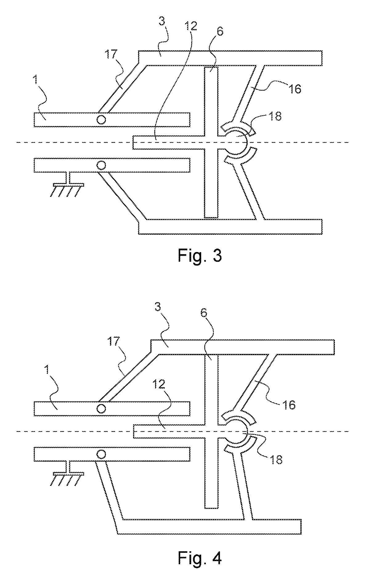
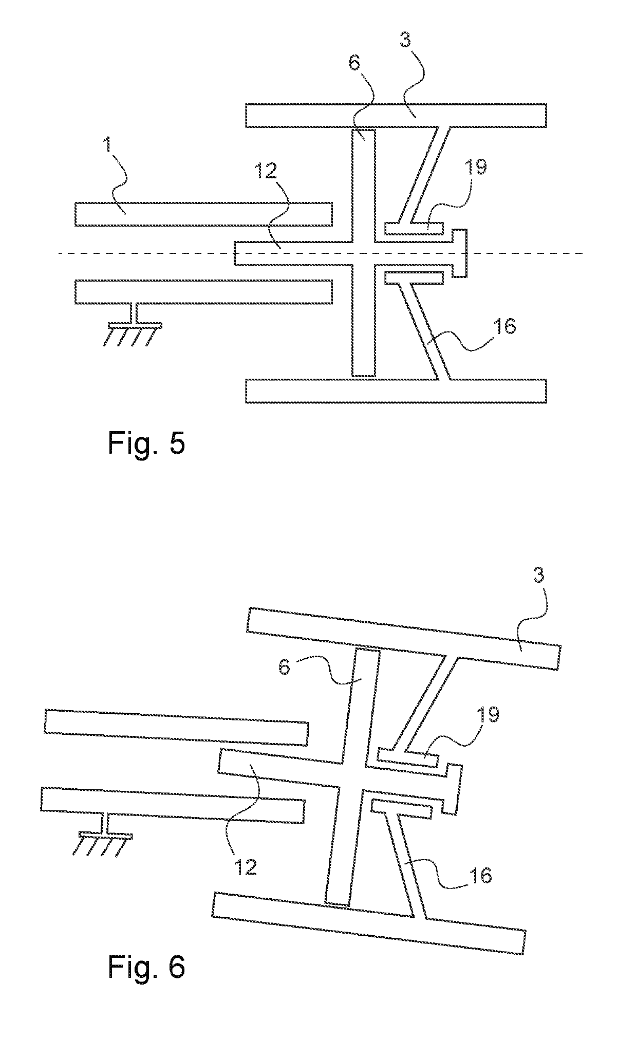
The power unit described in this patent helps prevent the nacelle (the part of the engine that holds the blades of the fan) from getting bent or deformed when it's subjected to mechanical stress. This ensures a consistent separation between the fan and nacelle, which leads to better engine efficiency.

Problems solved by technology

In effect, when a jet engine is mounted in a free air flow, the excess kinetic energy in the jet is lost.
Improving the efficiency of the propulsion of aircraft is currently a major issue, in order to reduce their specific consumption (that is to say the fuel consumption relative to the mass of the aircraft).

Method used


Image

  • Nacelle for an aircraft power unit
  • Nacelle for an aircraft power unit
  • Nacelle for an aircraft power unit

Examples


Embodiment Construction

[0029]Some embodiments will now be described with reference to the Figures.

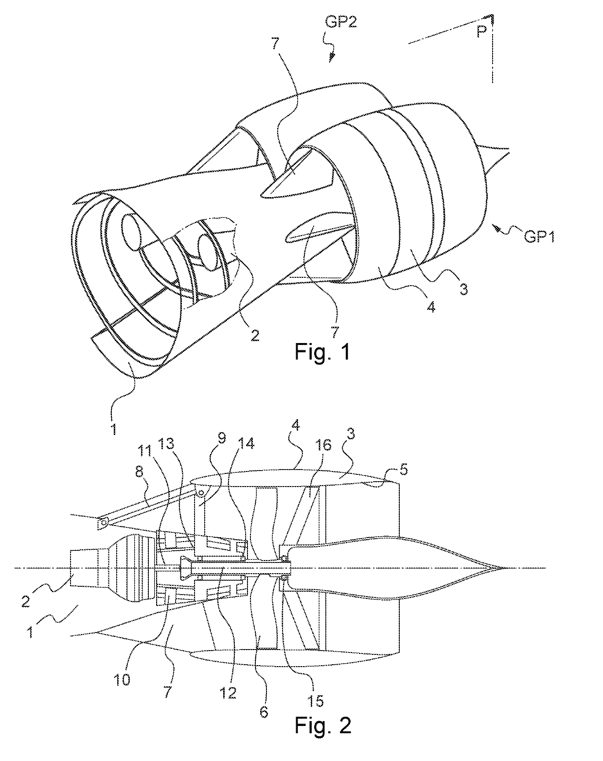
[0030]FIG. 1 represents an aircraft power unit and its installation on an aircraft according to an embodiment considered prior to the invention. More specifically, FIG. 1 represents a first power unit GP1 and a second power unit GP2 installed side by side in a fuselage rear portion 1. The power units and the fuselage rear portion 1 constitute the rear part of an aircraft. The power units GP1, GP2 are identical, such that just one of the power units GP1, GP2 is detailed hereinbelow, in this case the first power unit GP1, hereinafter designated “the power unit”.

[0031]The power unit comprises an engine 2 which is essentially included in the fuselage rear portion 1. The engine can be a turbine engine, in particular a turbojet engine, whose rear part can form the rear end part of the fuselage. In the example represented here, the turbine engine is positioned upstream of the fan, and the ejection cone is positioned...


PUM


Abstract

An aircraft power unit is disclosed having an engine, which an output shaft linked to a driveshaft of a fan positioned downstream of the engine. The fan is included in a duct formed by a nacelle of the power unit. The nacelle is linked to the driveshaft of the fan by a nacelle pivot formed downstream of the fan.

Description

CROSS REFERENCE TO RELATED APPLICATION[0001]This application claims priority to and incorporates by reference French Patent Application Number 1852198, filed Mar. 14, 2018.BACKGROUND1. Field of the Invention[0002]The disclosure generally relates to aircraft power units, and mores specifically to a nacelle for an aircraft power unit.2. Description of the Related Art[0003]Commercial aircraft generally have a general architecture having a fuselage, an airfoil comprising two wings, and a rear tail (and / or “duck” if necessary). Such aircraft may comprise one or more power units, which are commonly jet engines. The power units can be installed according to various configurations. They can for example be suspended under the airfoil by support pylons, or fixed to the rear of the fuselage by pylons or at the tail unit.[0004]In flight, the outer surfaces of the aircraft influence the flow of the air. In particular, in the movement of an aerodynamic profile in air, a boundary layer is created ...

Claims


Application Information

Patent Timeline
IPC IPC(8): B64D29/04B64D29/06B64D33/04B64D27/20
CPCB64D27/20B64D29/04B64D33/04B64D29/06F02K3/062Y02T50/60
Inventor COLMAGRO, JÉRÔMETOURIN, MATHIAS
Owner AIRBUS OPERATIONS SAS
Learn More