
Indoor unit for air conditioner

a technology for indoor units and air conditioners, applied in lighting and heating apparatus, heating types, separation processes, etc., can solve the problems of burden on upward and downward movement, the heavier the weight of the filter cleaner, etc., and achieve the effect of maintaining a clean indoor space, a clean and pleasant environment, and a clean filter

Active Publication Date: 2019-09-12
LG ELECTRONICS INC
View PDF0 Cites 9 Cited by
  • Summary
  • Abstract
  • Description
  • Claims
  • Application Information

AI Technical Summary

Benefits of technology

The present invention aims to provide a structure that allows a filter cleaner to move upward and downward while maintaining a predetermined distance from a filter positioned in upward and downward directions. The structure includes a connection housing that provides a space to receive a dust container, a flow path toward the dust container, and a structure connected to a suction fan. The invention also aims to provide a stable fixed structure of the dust container and a structure that allows dust to be smoothly introduced into the dust container. The technical effect of the invention is to improve the performance and efficiency of a filter cleaner.

Problems solved by technology

Besides, the more the elements is included in the filter cleaner, the heavier the weight of the filter cleaner becomes, and, in this case, upward and downward movement may require burden.

Method used


Image

  • Indoor unit for air conditioner
  • Indoor unit for air conditioner
  • Indoor unit for air conditioner

Examples


Embodiment Construction

[0087]Advantages and features of the present invention and a method of achieving the same will be clearly understood from embodiments described below in detail with reference to the accompanying drawings. However, the present invention is not limited to the following embodiments and may be implemented in various different forms. The embodiments are provided merely for complete disclosure of the present invention and to fully convey the scope of the invention to those of ordinary skill in the art to which the present invention pertains. The present invention is defined only by the scope of the claims. Throughout the present specification, like numbers refer to like elements.

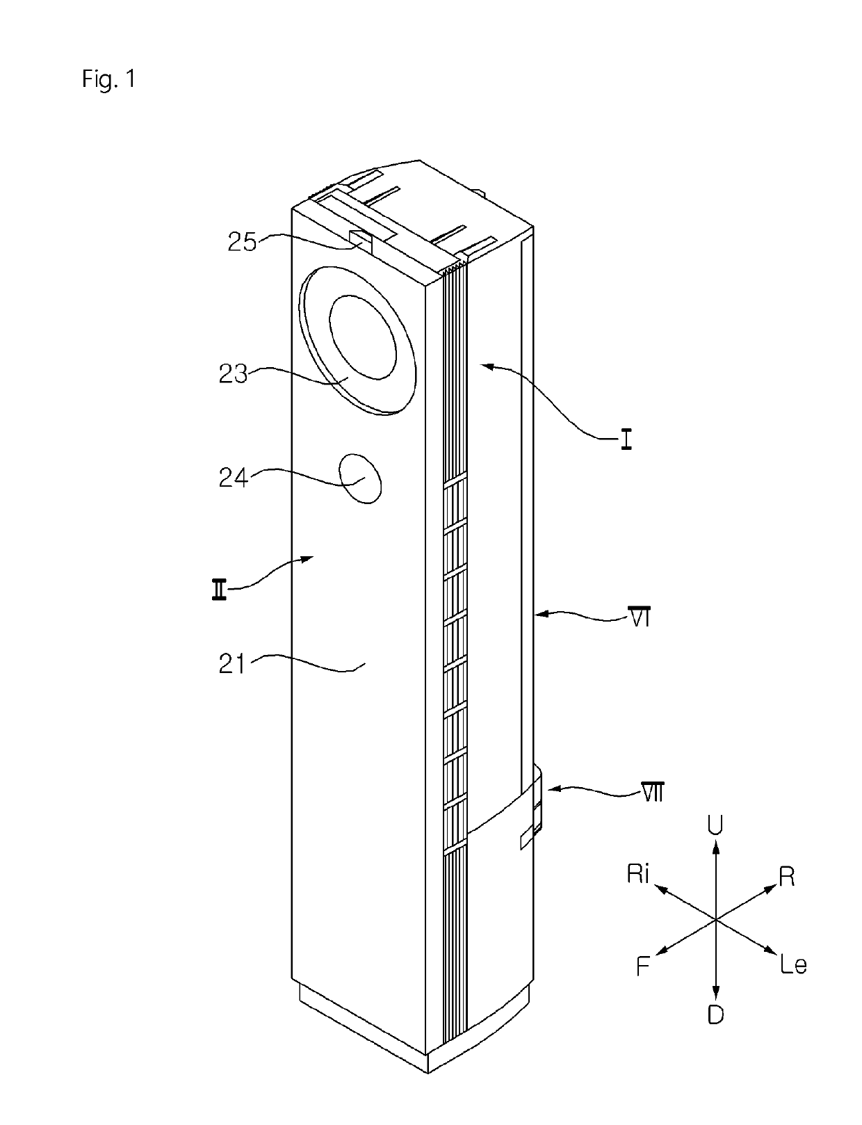
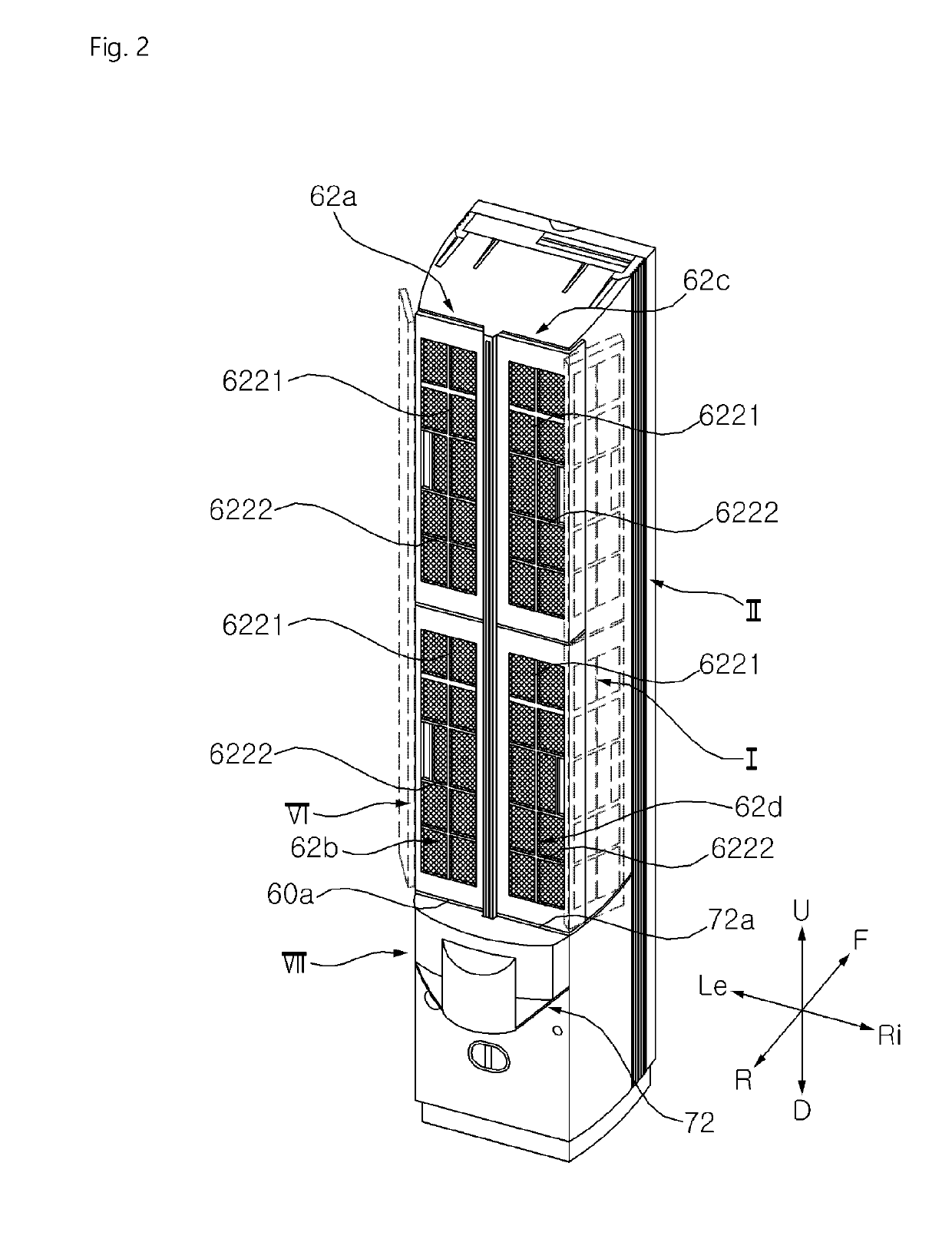
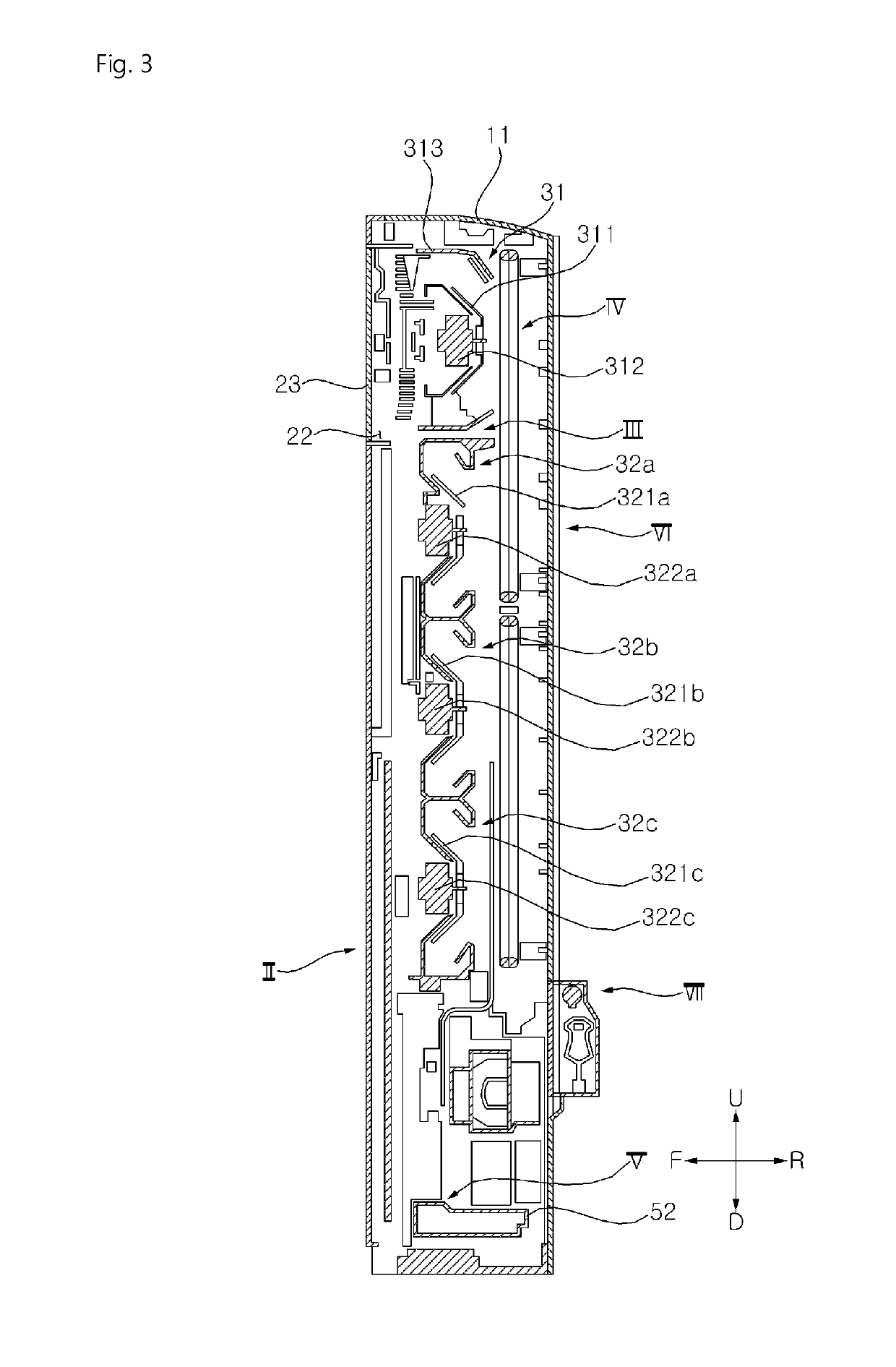
[0088]In the following description, the terms “first,”“second,” etc. are used only to avoid confusion between components, and do not indicate the sequence or importance of the components. The directions of “upward (U)”, “downward (D)”, “leftward (Le)”, “rightward (Ri)”, “forward (F)”, and “rearward (R)” in drawing...


PUM

PropertyMeasurementUnit
frictionaaaaaaaaaa
magnetic forceaaaaaaaaaa
rotationaaaaaaaaaa

Abstract

Disclosed is an indoor unit for an air conditioner. The indoor unit for the air conditioner according to the present invention includes: a cabinet assembly forming an external appearance of the indoor unit and having an air suction port formed in a rear of the cabinet assembly; a filter module disposed at the air suction port to filter dust contained in air being introduced through the air suction port; a filter cleaner configured to move upward and downward in a rear of the filter module to remove foreign substances stuck in the filter module; a guide rail vertically disposed on one side of the filter module and configured to guide upward and downward movement of the filter cleaner, wherein the filter cleaner comprises: a mobile gear configured to rotate while engaged with the guide rail to move the filter cleaner upward and downward with respect to the filter module, a gear motor configured to rotate the mobile gear, an agitator configured to rotate in friction with the filter module, a dust container disposed downward of the agitator and collecting foreign substances separated from the filter module due to the rotation of the agitator, and a guide roller bringing the filter cleaner into close contact with the filter module so that part of the agitator rotates while in contact with the filter module.

Description

CROSS-REFERENCE TO RELATED APPLICATION[0001]This application claims the priority benefit of Korean Patent Application No. 10-2018-0026970, filed on Mar. 7, 2018 and 10-2019-0017451, filed on Feb. 14, 2019 in the Korean Intellectual Property Office, the disclosure of which is incorporated herein by reference.BACKGROUND OF THE INVENTION1. Field of the Invention[0002]The present invention relates to an indoor unit for an air conditioner and, more particularly, to an indoor unit for an air conditioner, which includes a filter cleaner to clean a filter.2. Description of the Related Art[0003]An indoor unit for an air conditioner may adjust required indoor temperature by discharging air heat-exchanged with a refrigerant to an indoor space. The indoor unit for the air conditioner suctions indoor air through an air suction port, make the suctioned air to exchange heat with a refrigerant, and discharge the heat-exchanged air to an air discharge port.[0004]In indoor unit for the air conditione...

Claims


Application Information

Patent Timeline
Patent Type & Authority Applications(United States)
IPC IPC(8): B01D46/00F24F1/0073F24F3/16B01D46/48B01D46/12F24F8/108F24F8/90
CPCF24F2003/1639B01D46/0008B01D46/48B01D2279/50B01D46/0065B01D46/12F24F3/1603F24F1/0073F24F13/28F24F8/108F24F8/90F24F11/39F24F11/89F24F2221/22F24F1/005B01D46/681B01D46/44F24F11/30F24F13/24
Inventor CHOI, SUNGGYUKIM, KANGYOUNGLEE, EUNSUNLEE, JUNGWONBAE, JUNSEOKKANG, MYEONGGUGYEONG, GIYEONG
Owner LG ELECTRONICS INC
Learn More