Method and device of data capture

Active Publication Date: 2019-08-22
AU OPTRONICS CORP
View PDF0 Cites 2 Cited by
  • Summary
  • Abstract
  • Description
  • Claims
  • Application Information

AI Technical Summary

Benefits of technology

The invention provides a method and device for capturing data that can automatically adjust settings to ensure accurate signals at high transmission rates. This is achieved by adding an auxiliary clock signal with a different phase, sampling the data signal, generating edge information, and adjusting the clock signal based on the data signal state. This allows the device to learn and adjust for completeness of signals, ensuring accuracy of the received data.

Problems solved by technology

However, on a data transmission path, the data transmission rate is often limited due to resistive-capacitive delay (RC delay) and jitter.
However, since a phase difference is present between a clock signal and a data signal generated by a source driver via a clock-data-recovery (CDR) circuit, when data is captured, a set up time or a hold time is not in an optimal state, and as the transmission rate is increased to a certain extent, errors occur when data is received.
Moreover, due to differences in manufacturing processes and operation environments, the same equalization settings are not applicable to all displays.

Method used


Image

  • Method and device of data capture
  • Method and device of data capture
  • Method and device of data capture

Examples


Embodiment Construction

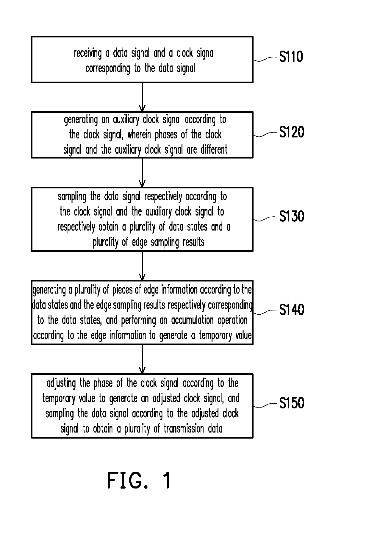
[0033]Referring to FIG. 1, FIG. 1 is a flowchart illustrating a data capture method according to an embodiment of the invention. In a process of the data capture method, in step S110, an operation of receiving a data signal and a clock signal corresponding to the data signal is performed. Next, in step S120, an auxiliary clock signal is generated according to a phase of the clock signal. For example, the auxiliary clock signal may be generated by changing the phase of the clock signal, such that a phase difference between the clock signal and the auxiliary clock signal is 180°, for example (the clock signal and the auxiliary clock signal are inverted signals to each other). Moreover, in step S130, the data signal is sampled according to the clock signal and a positive transition edge of the auxiliary clock signal to respectively obtain a plurality of data states and a plurality of edge sampling results. Specifically, each of the data states may be a low logic level or a high logic l...


PUM


Abstract

A data capture method and a data capture device are provided. The data capture method includes: receiving a data signal and a clock signal corresponding to the data signal; generating an auxiliary clock signal according to the clock signal, wherein phases of the clock signal and the auxiliary clock signal are different; sampling the data signal respectively according to the clock signal and the auxiliary clock signal to respectively obtain a plurality of data states and a plurality of edge sampling results; generating a plurality of pieces of edge information according to the data states and the corresponding edge sampling results, and performing an accumulation operation according to the edge information to generate a temporary value; and adjusting the clock signal according to the temporary value to generate an adjusted clock signal, and sampling the data signal according to the adjusted clock signal to obtain a plurality of transmission data.

Description

CROSS-REFERENCE TO RELATED APPLICATION[0001]This application claims the priority benefit of Taiwan application serial no. 107105764, filed on Feb. 21, 2018. The entirety of the above-mentioned patent application is hereby incorporated by reference herein and made a part of this specification.BACKGROUND OF THE INVENTIONField of the Invention[0002]The disclosure provides a data capture method and a data capture device, and in particular, to a data capture method and a data capture device that enhance data transmission rates by adding an auxiliary clock signal to enable the data capture device to learn to autonomously adjust parameters related to completeness of signals.Description of Related Art[0003]As display panel resolutions and frame rates increase, there is a higher demand for display data transmission rates. However, on a data transmission path, the data transmission rate is often limited due to resistive-capacitive delay (RC delay) and jitter. Therefore, many developments and ...

Claims


Application Information

Patent Timeline
IPC IPC(8): G06F1/08
CPCG06F1/08G09G3/20G06F3/1407G06F1/06G09G2320/0223G09G2370/00G09G2310/0264
Inventor FU, JHIH-SYUANCHUNG, CHUN-FANYANG, CHIH-FU
Owner AU OPTRONICS CORP
Why Eureka
Try Eureka