
Apparatus and method for measuring at least one optically effective object

a technology of optically effective objects and devices, applied in the direction of geometric properties/aberration measurement, structural/machine measurement, instruments, etc., can solve the problems of limited measurement devices and methods that can be carried out with them, limited measurement devices to the detection of special data, and calculations of data required for the edge processing of optical lenses. achieve the effect of simple and flexible manner

Active Publication Date: 2019-08-22
SCHNEIDER GMBH & CO KG
View PDF14 Cites 3 Cited by
  • Summary
  • Abstract
  • Description
  • Claims
  • Application Information

AI Technical Summary

Benefits of technology

The device and method described in this patent make it easy to measure objects that have an optical effect. The device is flexible and can be adjusted based on the data needed and the material being measured. Its unique design allows for quick and accurate results, improving efficiency and accuracy in optical measurements.

Problems solved by technology

The disadvantage here is that only the data required for the edge processing of the optical lens can be calculated.
This measuring device and the method that can be carried out with it are limited to the contactless scanning of the lens surface and the rapid determination of the lens type.
Also, this measuring device is limited to the detection of special data, namely surface defects in the lens.

Method used


Image

  • Apparatus and method for measuring at least one optically effective object
  • Apparatus and method for measuring at least one optically effective object
  • Apparatus and method for measuring at least one optically effective object

Examples


Embodiment Construction

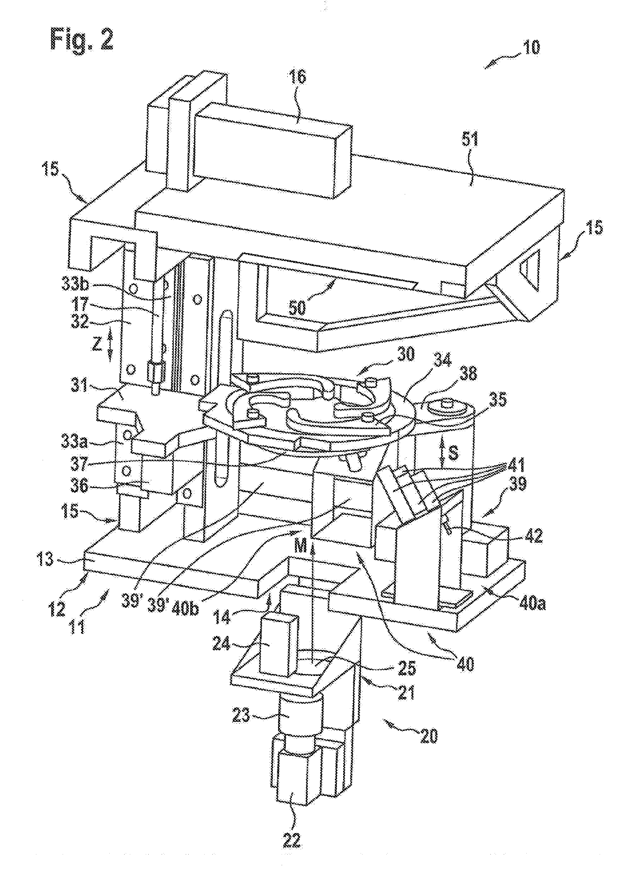
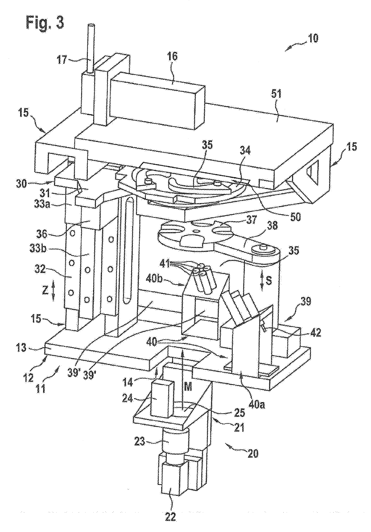
[0016]Various embodiments of the invention will now be described in detail with reference to the Figures. These figures are merely provided to assist in the understanding of the invention and are not intended to limit the invention in any way. One skilled in the art will recognize that various modifications and changes can be made to any of these embodiments without departing from the scope and spirit of the present invention.

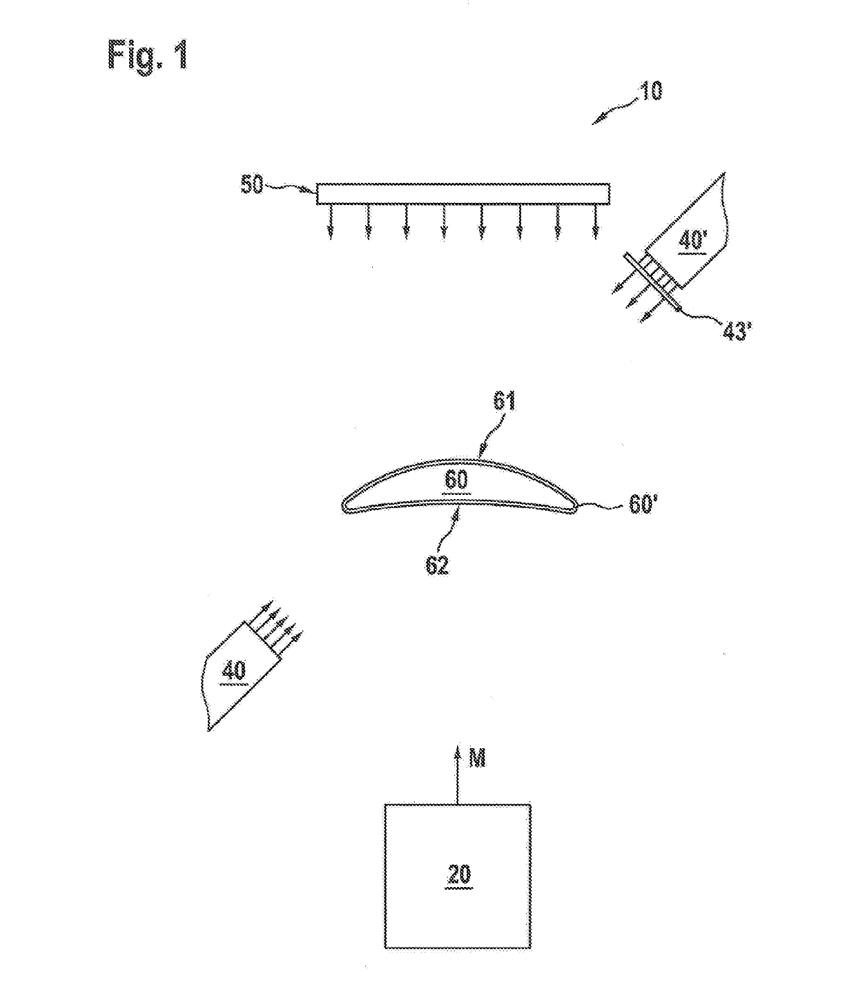
[0017]The device according to the invention as well as the measuring method according to the invention make it possible to measure the optically effective object in any machining stage under the same or comparable boundary conditions, adapted to the requirements of the individual case.

[0018]Both the device according to the invention and the method according to the invention can be integrated into an existing processing system for the optically effective object to be measured, both with regard to existing processing devices and with respect to existing processin...


PUM


Abstract

A device and method are described having / using at least a first radiation source and a second source of radiation, at least one measurement or detection device as well as at least one evaluation system with the first radiation source and second radiation source either oriented towards a top or bottom side of the optically effective object, or together oriented towards the top or bottom of the optically effective object, whereby at least the first radiation source emits reflective radiation towards the optically effective object and / or excitation radiation emitted for the stimulation of luminescence radiation in the material of the optically effective object and / or in the coating material of the optically effective object, and whereby the second radiation source at least emits radiation that penetrates through the optically effective object.

Description

CROSS-REFERENCE TO RELATED APPLICATIONS[0001]This application claims priority to German National Application DE 10 2018 001 385.6 filed Feb. 21, 2018 and German National Application DE 10 2018 007 463.4 filed Sep. 21, 2018.BACKGROUND OF THE INVENTION[0002]The present invention relates to a device for measuring at least one optically effective object, comprising a radiation source, a measuring device, and means for holding at least one optically effective object between the radiation source and the measuring device. The present invention further relates to a method for measuring at least one optically effective object having a top side and a bottom side, and wherein at least one optically effective object is irradiated with a measuring radiation and the resulting radiation is measured.[0003]International patent application WO 2016 / 095939 A1 describes a method and a device for the edge processing of an optical lens, wherein the device has a measuring instrument for determining the ori...

Claims


Application Information

Patent Timeline
Patent Type & Authority Applications(United States)
IPC IPC(8): G01M11/02
CPCG01M11/0235G01M11/0207G01M11/0285G01M11/0228G01M11/0278G01B11/2513G01M11/025G01M11/0257G01B11/255
Inventor SCHNEIDER, GUNTERHUTTENHUIS, STEPHANSCHNEIDER, SEBASTIAN
Owner SCHNEIDER GMBH & CO KG
Learn More