
Anchoring system for attaching a prosthesis to a human body

a technology for attaching systems and prostheses, which is applied in the field of anchoring systems for attaching prostheses to human bodies, can solve the problems of requiring new surgical operations and the risk of fixture loosening, and achieve the effect of improving the anchoring system

Active Publication Date: 2019-08-22
INTEGRUM
View PDF0 Cites 1 Cited by
  • Summary
  • Abstract
  • Description
  • Claims
  • Application Information

AI Technical Summary

Benefits of technology

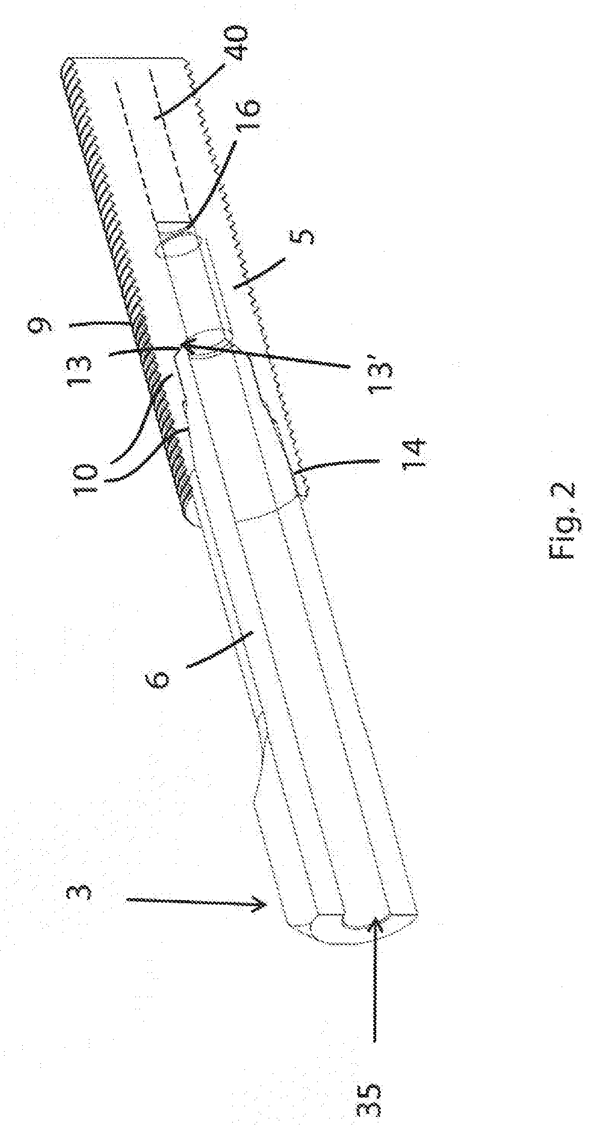
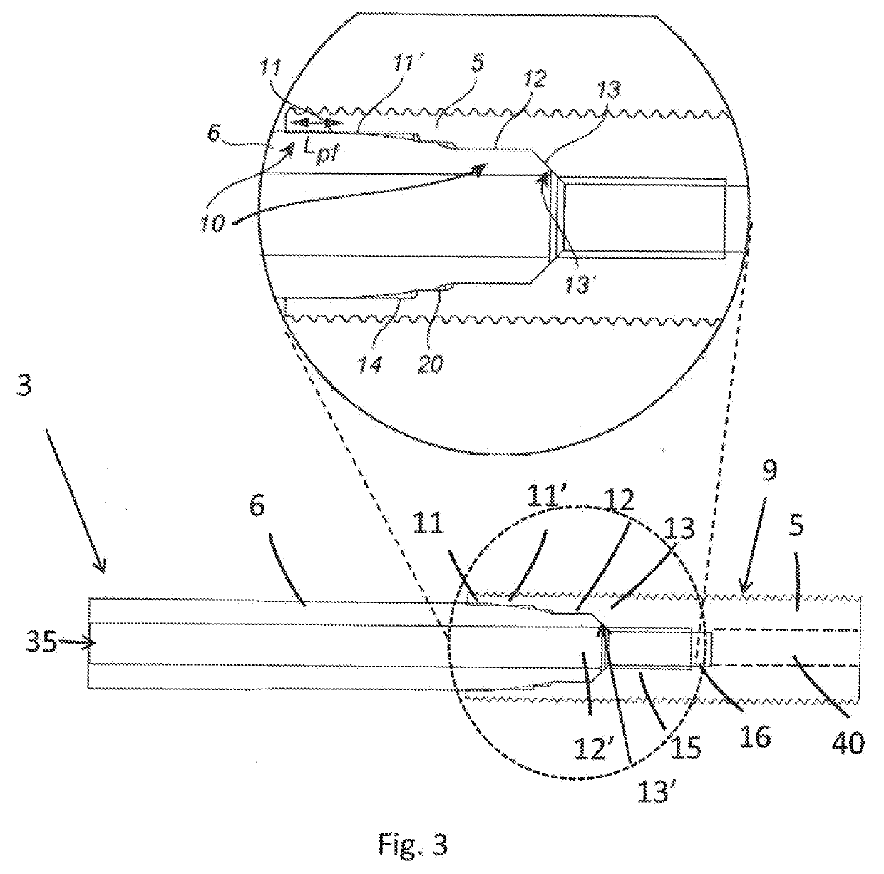
The invention aims to improve the anchoring system of dental implants by increasing its mechanical strength, specifically fatigue strength, stability, and robustness. The conical portion of the abutment and the corresponding conical portion of the anchoring element provide a stable contact point at the most proximal end of the connection area, ensuring stability and load distribution. The outer profile of the anchoring element includes a first thread portion with a larger thread depth than a second thread portion, which increases the bone anchoring surface area and strength and maintains secure bone-anchoring. The second thread portion extends beyond the connection area, further improving strength and stability. The press-fit portion is conical and includes a straight portion adjacent to the conical press-fit portion to provide stress relief and avoid high stress singularities.

Problems solved by technology

For example, if the anchoring of the anchoring element (e.g. a “fixture”) is disturbed then there is a risk of loosening of the fixture and a new surgical operation might be required.

Method used


Image

  • Anchoring system for attaching a prosthesis to a human body
  • Anchoring system for attaching a prosthesis to a human body
  • Anchoring system for attaching a prosthesis to a human body

Examples


Embodiment Construction

[0045]The present invention will now be described more fully hereinafter with reference to the accompanying drawings, in which currently preferred embodiments of the invention are shown. This invention may, however, be embodied in many different forms and should not be construed as limited to the embodiments set forth herein; rather, these embodiments are provided for thoroughness and completeness, and fully convey the scope of the invention to the skilled person. Like reference characters refer to like elements throughout.

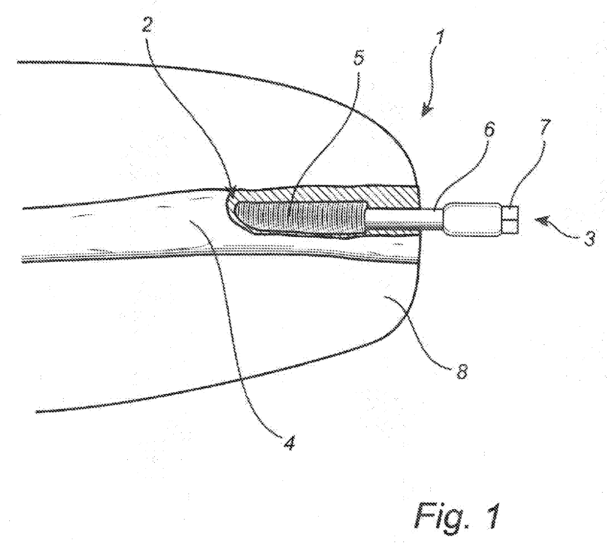
[0046]FIG. 1 is a schematic illustration of an anchoring system 1 placed in the femur bone 4 of an amputation stump for attaching a prosthesis. The anchoring system has a proximal end 2 and a distal end 3. The proximal end 2 of the anchoring system is anchored to the bone tissue 4 and the distal end 3 links the system to an external prosthetic component (not shown here), such as a limb prosthesis or prosthetic knee. The anchoring system 1 comprises an anchoring el...


PUM

PropertyMeasurementUnit
Angleaaaaaaaaaa
Angleaaaaaaaaaa
Angleaaaaaaaaaa

Abstract

The present invention relates to an anchoring system for attaching a prosthesis to a human body, comprising: an anchoring element, an abutment, an abutment screw for attaching the abutment to the anchoring element, the anchoring element comprises a connection area for the abutment, the connection area comprising a press-fit portion such that the abutment is attached to the anchoring element in the connection area by a press-fit connection, wherein the connection area comprises an anti-rotation geometry and the abutment comprising a corresponding mating anti-rotation geometry proximal to the press-fit portion, and where in the connection area comprises a conical portion proximal to the anti-rotational geometry forming a mating geometry for a corresponding conical portion in the through-hole of the abutment.

Description

TECHNICAL FIELD[0001]The present invention relates to an anchoring system for attaching a prosthesis to a human body.BACKGROUND OF THE INVENTION[0002]Generally, osseointegrated prostheses for rehabilitation of amputees (OPRA system) are known and have been developed and commercialized by Integrum AB, Mölndal, Sweden. The OPRA system is currently used to anchor limb prostheses by means of a titanium implant that is surgically inserted into the bone. Generally, the OPRA system consists of a titanium screw implanted inside the bone and which serves as a fixture for an abutment, a central screw, and the abutment which is partly inserted inside the fixture and partly exiting the bone and stump so that the attachment of the artificial limb can be arranged at the head of the abutment.[0003]In the present OPRA system a first surgery is carried out in which the fixture is implanted in the long bone and the central screw is inserted into the fixture. During a healing period of about six month...

Claims


Application Information

Patent Timeline
IPC IPC(8): A61C8/00A61F2/78
CPCA61C8/0071A61F2/78A61C8/0066A61C8/0037A61F2002/7868A61F2002/7875A61F2002/7887A61F2/50A61F2/30749A61F2002/30143A61F2002/30153A61F2002/30154A61F2002/30156A61F2002/30329A61F2002/30331A61F2002/30332A61F2002/30345A61F2002/30367A61F2002/30886A61F2220/0025A61F2220/0033A61F2230/0067A61C8/006A61C8/0068A61C8/0069A61F2002/3021A61F2002/30392A61F2002/30393A61F2002/30395A61F2002/30405A61F2002/30413A61F2002/30433A61F2002/30507A61F2220/0041A61C8/0048A61C8/005A61C8/0054A61C8/0074A61F2002/30214A61F2002/30354A61F2310/0058
Inventor BRANEMARK, RICKARDBJORNSDOTTIR, MARTALOPEZ, MARIAHALLENSTVEDT, ODDBJORNMANSSON, STAFFAN
Owner INTEGRUM
Learn More