
Fluid control valve and manifold

Pending Publication Date: 2019-08-01
BAYER HEALTHCARE LLC
View PDF3 Cites 1 Cited by
  • Summary
  • Abstract
  • Description
  • Claims
  • Application Information

AI Technical Summary

Benefits of technology

The sliding valve member in this patent creates drag that increases as it deflects.

Problems solved by technology

In fluid injection systems having multiple syringes, the problem of inaccurate volume delivery may be further exacerbated when fluids from the multiple syringes are injected simultaneously at different pressures.
As a result of the pressure differential between the two fluids, the fluid injected under higher pressure may tend to bleed into the lower pressure side of the system.
As a result, some amount of delivery volume is lost due to the expansion, or capacitance, of the lower pressure side components.
However, these valves do not generally provide for dual flow where mixtures of the two or more fluids are injected at the same time.

Method used


Image

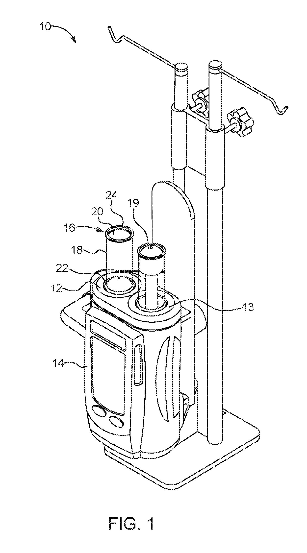
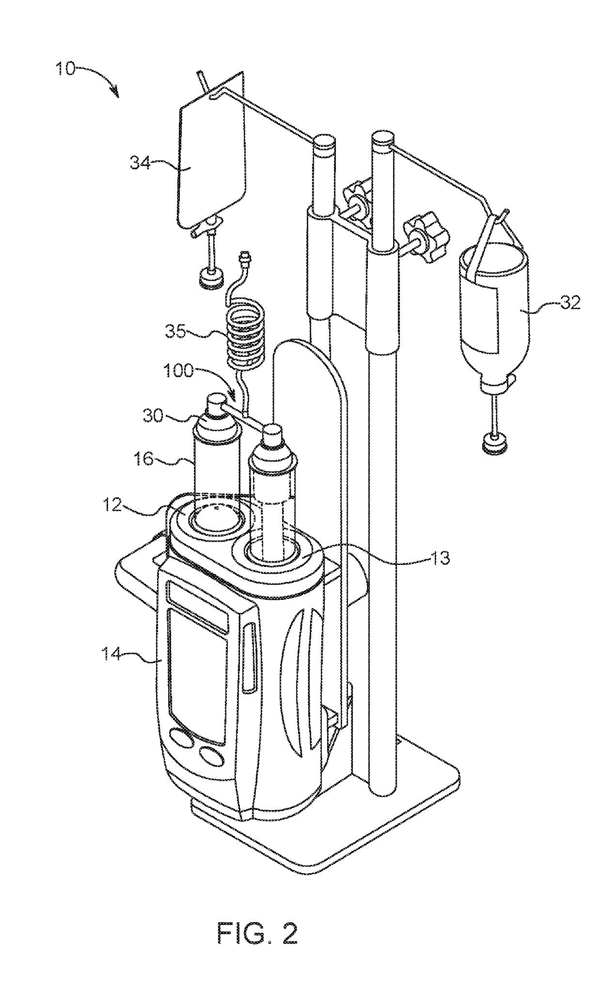
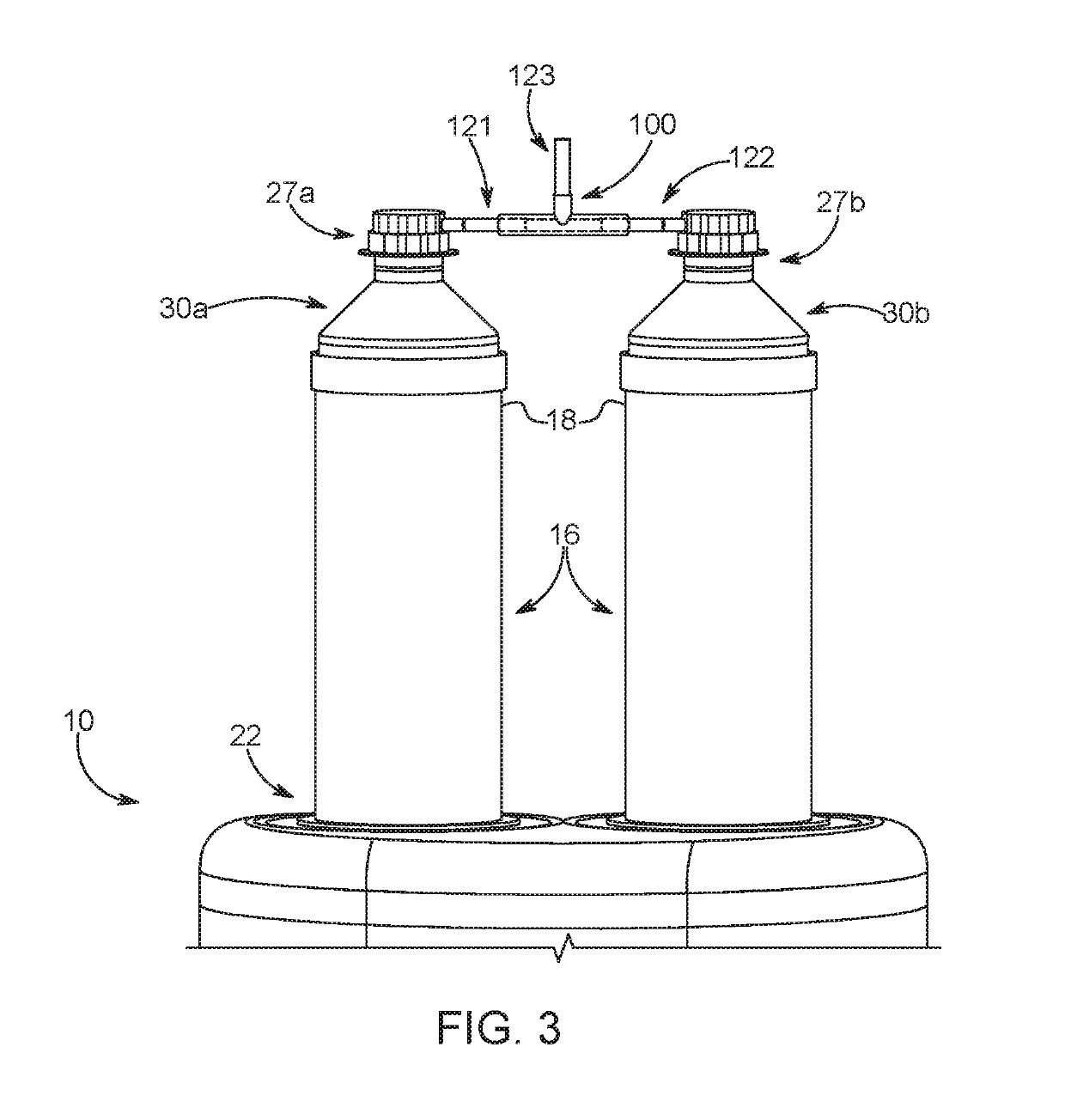
  • Fluid control valve and manifold
  • Fluid control valve and manifold
  • Fluid control valve and manifold

Examples


Embodiment Construction

[0087]As used in the specification, the singular form of “a”, “an”, and “the” include plural referents unless the context clearly dictates otherwise.

[0088]For purposes of the description hereinafter, the terms “upper”, “lower”, “right”, “left”, “vertical”, “horizontal”, “top”, “bottom”, “lateral”, “longitudinal”, and derivatives thereof shall relate to the components as they are oriented in the drawing figures.

[0089]Spatial or directional terms, such as “left”, “right”, “inner”, “outer”, “above”, “below”, and the like, are not to be considered as limiting as the invention can assume various alternative orientations.

[0090]When used in relation to a syringe and / or a pressure jacket, the term “proximal” refers to a portion of a syringe and / or a pressure jacket nearest to an injector when a syringe and / or a pressure jacket is oriented for connecting to an injector. The term “distal” refers to a portion of a syringe and / or a pressure jacket farthest away from an injector when a syringe a...


PUM


Abstract

A fluid control valve for use in a fluid delivery system for delivering fluid to a patient includes a valve body defining an internal chamber, a first inlet port for receiving a first inlet tube, a second inlet port for receiving a second inlet tube, an outlet port, and a sliding valve member slidably disposed in the internal chamber. The first inlet tube defines a first inlet lumen axially aligned with the internal chamber. The second inlet tube defines a second inlet lumen axially aligned with the internal chamber. The sliding valve member includes a first sealing end and second sealing end. The sliding valve member is positionable in a first operating state, a second operating state, and a third operating state based on a flow differential between the first inlet lumen and the second inlet lumen.

Description

CROSS REFERENCE TO RELATED APPLICATIONS[0001]The present application claims priority to U.S. Provisional Patent Application No. 62 / 409,054, filed Oct. 17, 2016, entitled “Fluid Control Valve and Manifold”, U.S. Provisional Patent Application No. 62 / 463,200, filed Feb. 24, 2017, entitled “Syringe Cap”, and U.S. Provisional Patent Application No. 62 / 513,413, filed May 31, 2017, entitled “Sliding Mixing Valve For Dual Syringe Medical Injector”, the disclosures of all of which are hereby incorporated by reference in their entirety.BACKGROUND OF THE DISCLOSUREField of the Disclosure[0002]The present disclosure relates generally to fluid control valves and manifolds for use in a multi-syringe fluid injector. More specifically, the disclosure relates to fluid control valves and manifolds for substantially isolating fluid pressure in a first syringe from fluid pressure in a second syringe based on a pressure or fluid flow differential between the first syringe and the second syringe. Additi...

Claims


Application Information

Patent Timeline
IPC IPC(8): A61M39/22A61M5/31A61M5/00
CPCA61M39/223A61M5/31A61M5/007A61M2039/224A61M2039/2486A61M2039/1083A61M2039/1088A61M5/1408A61M5/16827A61M2039/2433A61M5/2066A61M2039/242
Inventor SPOHN, MICHAELCOWAN, KEVINCAIN, BRIANBERRY, DAVIDFENTRESS, JAMESORENSTEIN, DAVIDDEDIG, JAMESTUCKER, BARRY
Owner BAYER HEALTHCARE LLC
Learn More