
Optical Probe Using Multimode Optical Waveguide and Proximal Processing

a multi-mode optical waveguide and optical probe technology, applied in the direction of optical radiation measurement, diagnostics using spectroscopy, instruments, etc., can solve the problems of insufficient flexibility, existing techniques, and single-mode fiber alone not being able to perform spatial 2d or 3d imaging,

Active Publication Date: 2019-07-11
SWANSON ERIC +1
View PDF0 Cites 17 Cited by
  • Summary
  • Abstract
  • Description
  • Claims
  • Application Information

AI Technical Summary

Benefits of technology

The present patent is about a new technology for delivering and collecting light for optical imaging and therapy applications. The technology uses a special optical waveguide to deliver and collect light at the end of a single-mode or multi-mode fiber. This allows for better imaging and therapy in hard-to-reach areas of the body. The technology also includes a processing system and various optical components to improve image quality and reliability. The patent aims to overcome limitations of existing techniques and improve the performance of optical imaging and therapy devices.

Problems solved by technology

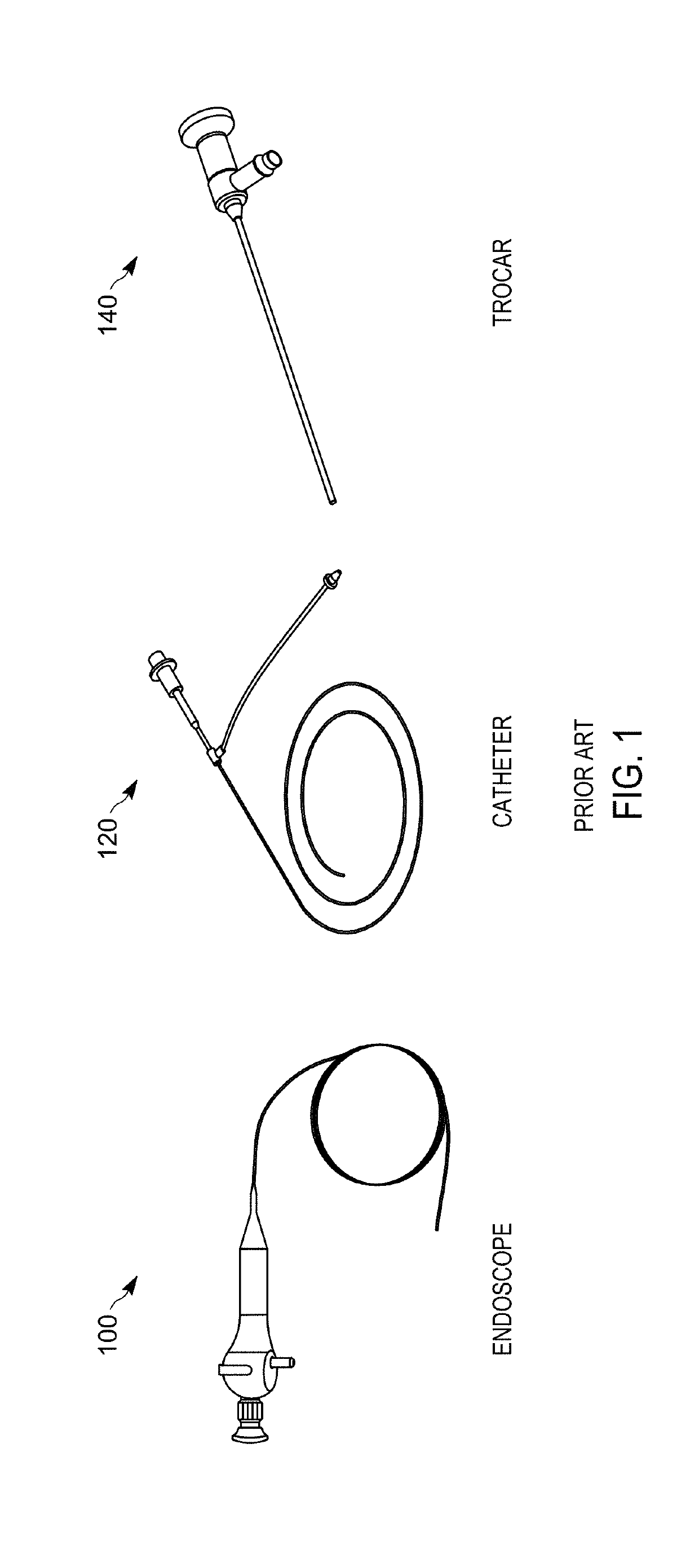
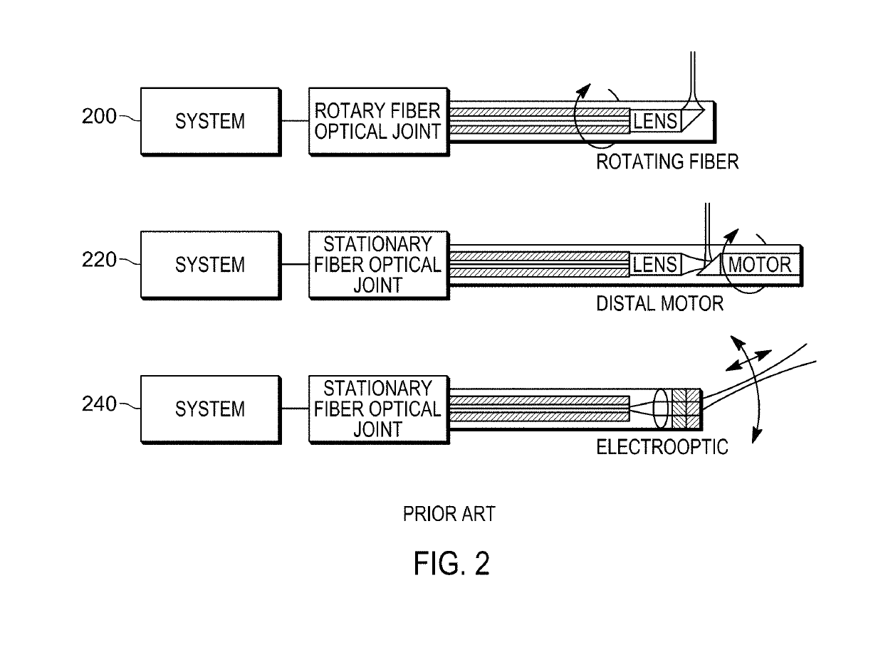
Single-mode optical fibers are inexpensive and flexible and commonly used to transmit light along an endoscope, but single-mode fiber by itself typically cannot perform spatial 2D or 3D imaging.
For many important medical and non-medical applications, these existing techniques suffer from a variety of significant limitations such as: the endoscopic probe being too thick and / or not flexible enough to access important regions within the human body; an inability to fit inside existing ports of clinical instruments; the endoscope or the system it attaches being too expensive; the endoscope being less reliable than desired; the scanning mechanism introducing optical image artifacts, such as non-uniform rotation distortion.

Method used


Image

  • Optical Probe Using Multimode Optical Waveguide and Proximal Processing
  • Optical Probe Using Multimode Optical Waveguide and Proximal Processing
  • Optical Probe Using Multimode Optical Waveguide and Proximal Processing

Examples


Embodiment Construction

[0031]The present teaching will now be described in more detail with reference to exemplary embodiments thereof as shown in the accompanying drawings. While the present teaching is described in conjunction with various embodiments and examples, it is not intended that the present teaching be limited to such embodiments. On the contrary, the present teaching encompasses various alternatives, modifications and equivalents, as will be appreciated by those of skill in the art. Those of ordinary skill in the art having access to the teaching herein will recognize additional implementations, modifications, and embodiments, as well as other fields of use, which are within the scope of the present disclosure as described herein.

[0032]Reference in the specification to “one embodiment” or “an embodiment” means that a particular feature, structure, or characteristic described in connection with the embodiment is included in at least one embodiment of the teaching. The appearances of the phrase...


PUM


Abstract

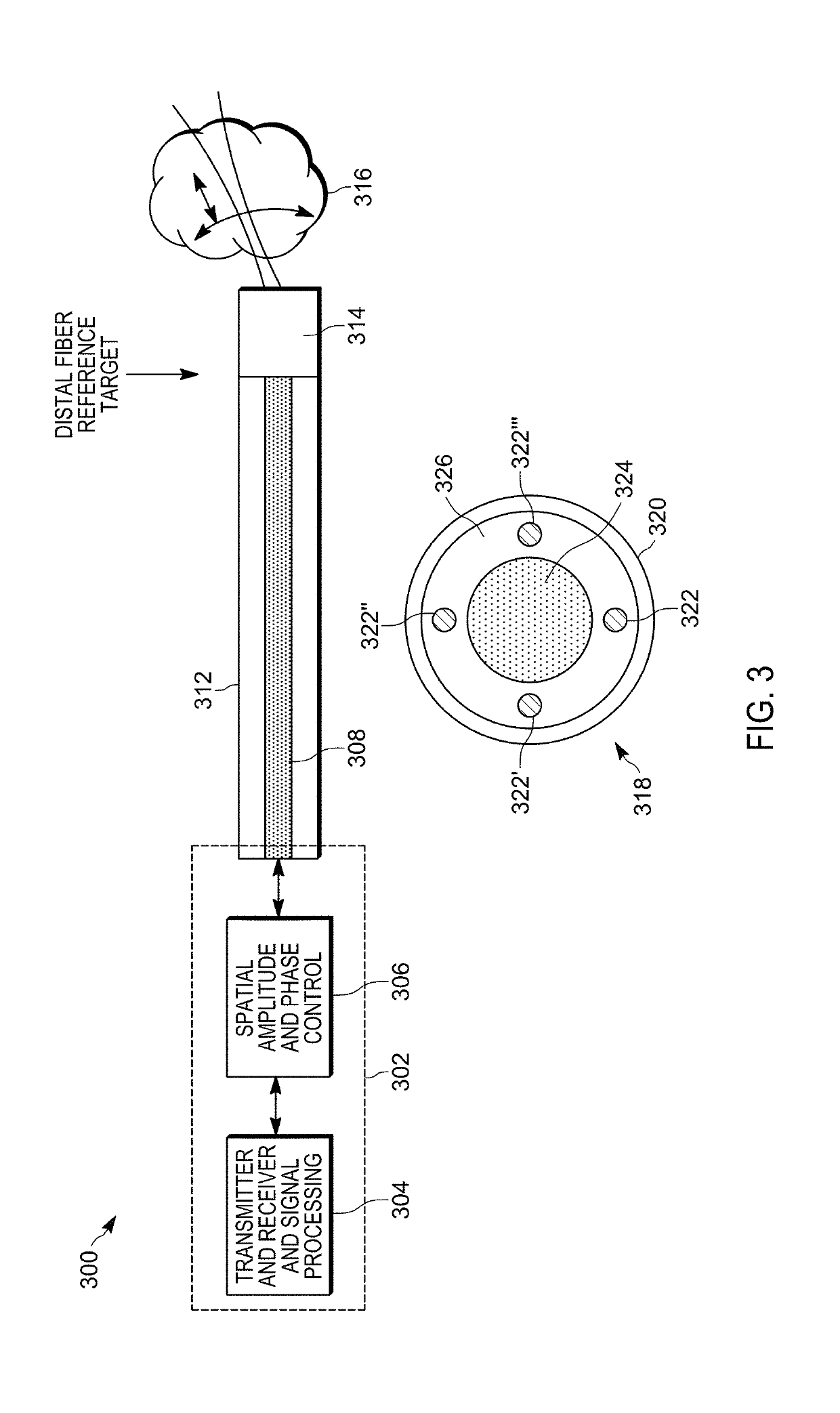
An optical probe includes an optical source that generates an optical beam that propagates from a proximal end to a distal end of an optical fiber that imparts a transformation of a spatial profile of the optical beam. An optical control device imparts a compensating spatial profile on the optical beam that at least partially compensates for the transformation of the spatial profile of the optical beam imparted by the optical fiber in response to a control signal from a signal processor. A distal optical source generates a calibration light that propagates through the one or more optical waveguides from the distal end to the proximal end of the optical fiber. An optical detector detects the calibration light and generates electrical signals in response to the detected calibration light. The signal processor generates the control signal to instruct the optical control device to impart the compensating spatial profile on the optical beam that at least partially compensates for the transformation of the spatial profile of the optical beam imparted by the optical fiber.

Description

[0001]The section headings used herein are for organizational purposes only and should not to be construed as limiting the subject matter described in the present application in any way.INTRODUCTION[0002]The present teaching relates to medical and non-medical applications for delivering and / or collecting light, and / or performing optical imaging and / or performing optical therapy of a sample at the distal end of an optical waveguide. In some embodiments, optical properties of a sample are determined. Optical properties can include, for example, absorption, reflection, refractive index, birefringence, dispersion, fluorescence, and other properties and this can be a function of wavelength and be at a point, a small volume, and / or spatially or spectrally resolved along one dimension, or multiple dimensions.[0003]There are many medical and non-medical needs for performing optical imaging of a sample (e.g. human organ or sample in hard to reach places). This includes within the human body ...

Claims


Application Information

Patent Timeline
IPC IPC(8): G05D25/02G02B6/04A61B1/06G01J3/44
CPCG05D25/02G02B6/04A61B1/06G01J3/4406G01J3/44G01J3/0218A61B1/07A61B1/00172A61B5/0066A61B5/0084A61B1/00057A61B1/043G02B6/34G02B6/262G02B6/3624A61B5/0075A61B2560/0223G02B6/02042G02B6/0288A61B1/0605
Inventor SWANSON, ERICKREMP, TRISTANWESTBROOK, PAUL S.DIGIOVANNI, DAVID
Owner SWANSON ERIC
Learn More