
A coupling device, associated parts and a method of use thereof

a technology of coupling device and associated parts, which is applied in the direction of building components, building reinforcements, constructions, etc., can solve the problems of reducing the efficiency of the reinforced concrete element, affecting the efficiency of the system, and corroding the other elements in the reinforcing bar cage, so as to achieve the effect of increasing interferen

Active Publication Date: 2019-07-11
HOLMES SOLUTIONS
View PDF0 Cites 0 Cited by
  • Summary
  • Abstract
  • Description
  • Claims
  • Application Information

AI Technical Summary

Benefits of technology

The invention is a pin that is designed to automatically increase its size and interfere with the movement of its neighboring parts when it is subject to external pressure. This increases the chance of them fitting together and locking into place, making a more robust connection.

Problems solved by technology

If the coupling device or part thereof does protrude beyond the transverse steel, then it may corrode or cause corrosion of the other elements in the reinforcing bar cage.
This in turn reduces the efficiency of the reinforced concrete element and places an impairment on the efficiency of the system.
This constraint may constrain structure, design and / or increase cost.
For example, under loading imposed by a large earthquake, a concrete element may become cracked and deformed.
A further design issue associated with axial stress is material change in dimension in an opposing direction due to Poisson's effect.
This Poisson's effect can make it difficult to couple to a material under high levels of axial tension stress because the high strain in the direction of load will result in a large reduction in cross sectional area.
This will result in the relative diameter of the coupling device to that of the coupled element to decrease under load, thereby increasing the difficulty of maintaining a high coupling capacity.
Based on the inventors' experience, art coupling devices have limitations and drawbacks associated with one or more of the above design constraints that comprise the art device performance and versatility.

Method used


Image

  • A coupling device, associated parts and a method of use thereof
  • A coupling device, associated parts and a method of use thereof
  • A coupling device, associated parts and a method of use thereof

Examples


working examples

[0220]For the purposes of the example below and for ease of reading, reference is made towards coupling reinforcing steel (being the elongated element or elements), the coupling sleeve being a tubular steel sleeve and the deformation means being nail shaped pins with a sharpened point and a head. This should not be seen as limiting as other applications may be also use the device, parts, tool or method described.

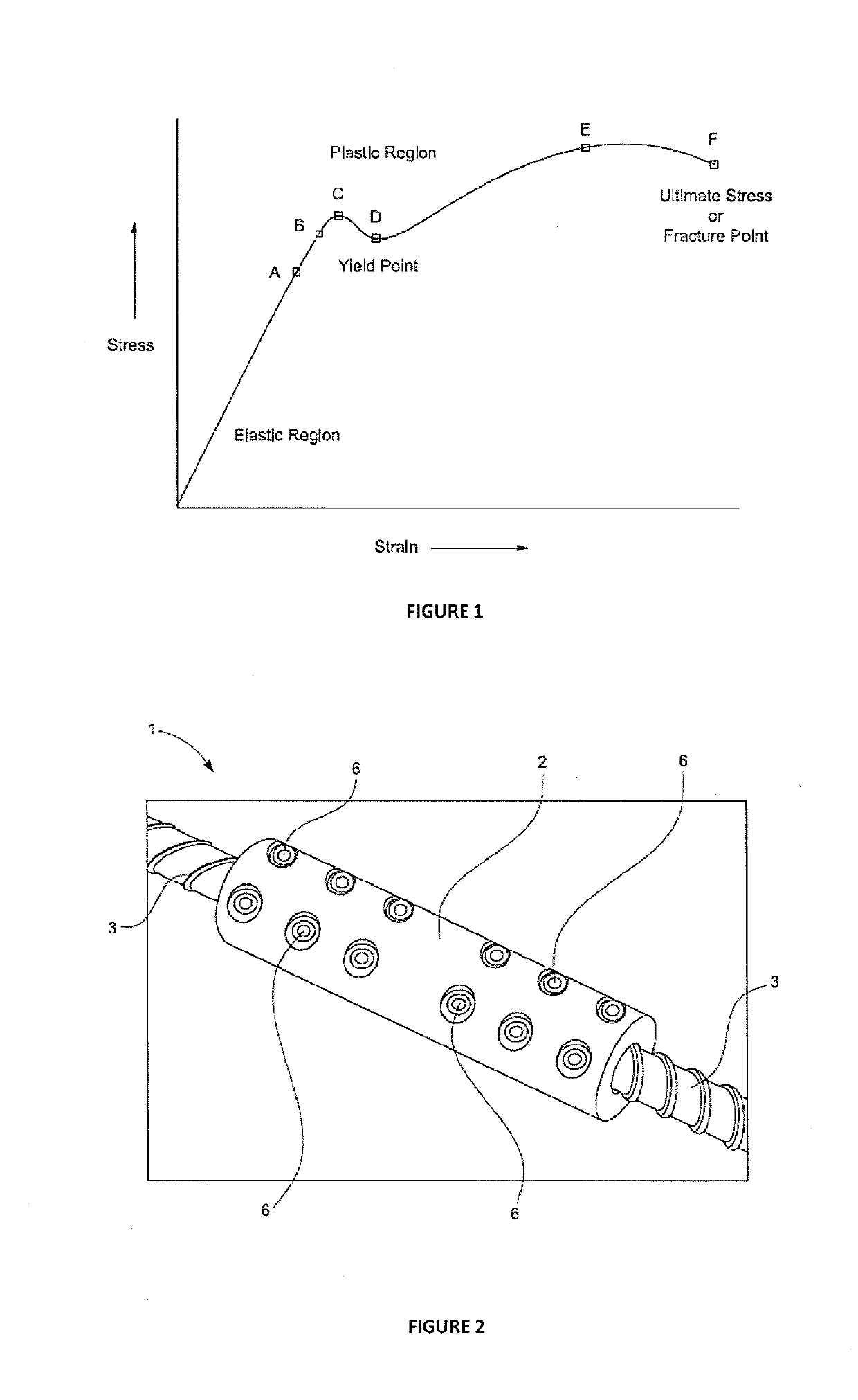
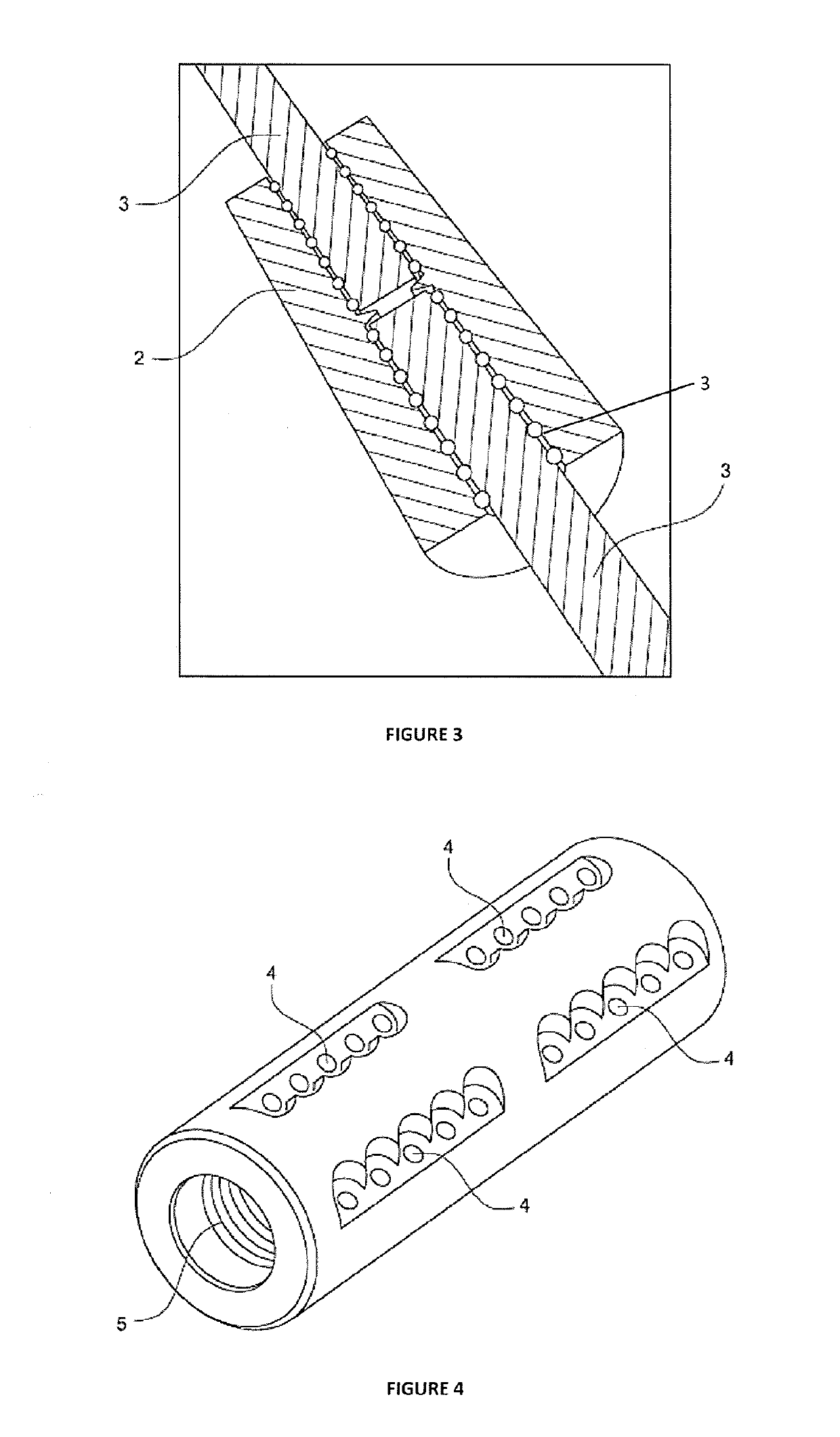
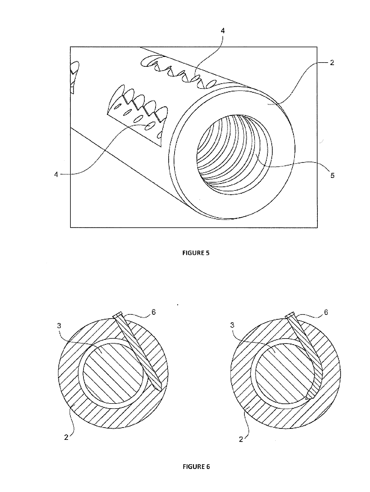
[0221]Referring to FIGS. 2 and 3, the inventors have designed a coupling device 1 consisting of a sleeve 2 into which the elongated element 3 or elements 3 to be coupled is / are inserted. In the embodiment shown in the Figures, the sleeve 2 is tubular with first and second ends. The elongated element 3 or elements 3 is / are elongated with first and second ends and a mid-section between the ends. Various rounded shapes or polygonal shapes may be used for the sleeve 2 and / or elongated element(s) 3 and the circular shapes shown are given by way of example only.

[0222]The sleeve 2 ...


PUM


Abstract

Described herein is a coupling device, associated parts and a method of use thereof. In one aspect, a coupling device is described comprising a sleeve with an inner surface that encloses at least part of at least one elongated element to be coupled; and at least one deformation means fitted with interference between, and causing local deformation about, at least part of the inner surface of the sleeve and / or an adjacent outer surface of the at least one elongated element. A deformation means insertion tool, a coupling sleeve, a deformation means, and a method of coupling at least one element are also described. The described coupling device, associated parts and a method of use offer the ability to couple together different elements in a strong and / or ductile manner, coupling being tuneable as needed to suit the preferred application. The coupling described may overcome art issues associated with bulky size of coupling, in particular, radial protrusion. The coupling may also increase the coupling force therefore increase the load that may be managed across the coupling device. Further, the way the parts are assembled may minimise generation of localised points of stress therefore also increasing the load that may be managed across the coupling device.

Description

RELATED APPLICATIONS[0001]This application derives priority from New Zealand patent application number 724218 incorporated herein by reference.TECHNICAL FIELD[0002]Described herein is a coupling device, associated parts and a method of use thereof. The coupling device may utilise material deformation on assembly in order to achieve coupling.BACKGROUND ART[0003]In many applications there is the need to join to, or couple with, elements. One such application is in reinforced concrete where reinforcing steel that is placed into the concrete is typically supplied in discrete lengths. There are many locations where the reinforcing steel must continue for a length longer than the discrete length supplied, and it becomes necessary to join multiple lengths together. One means of achieving this is to overlap the reinforcing steel over a long distance and use the surrounding concrete to provide transfer of the loads between the overlapping bars. An alternative means is to use a coupling devic...

Claims


Application Information

Patent Timeline
Patent Type & Authority Applications(United States)
IPC IPC(8): E04C5/16
CPCE04C5/165E04C5/16F16B7/0406
Inventor ALLINGTON, CHRISTOPHER JAMESDIEHL, ANDREW KARLSCOTT, PETER JOHNWOODS, BENJAMINGIBSON, JAMES GRAY
Owner HOLMES SOLUTIONS
Learn More