
Apparatus and Method for Detecting the Rotation of a Rod-String in a Wellbore

Pending Publication Date: 2019-07-04
PHILLIPS WALTER
View PDF6 Cites 6 Cited by
  • Summary
  • Abstract
  • Description
  • Claims
  • Application Information

AI Technical Summary

Benefits of technology

The patent describes a sensing device that uses a barometer to determine pressure and elevation. This device is placed on a polished rod to measure the motion of a pumping unit during a single stroke. The device also includes an accelerometer and gyroscope to measure rotational deflection. These sensors provide accurate readings and can be calibrated for consistent use. The technical effect of this invention is to provide a more precise and accurate method for measuring the operational state of a pumping unit.

Problems solved by technology

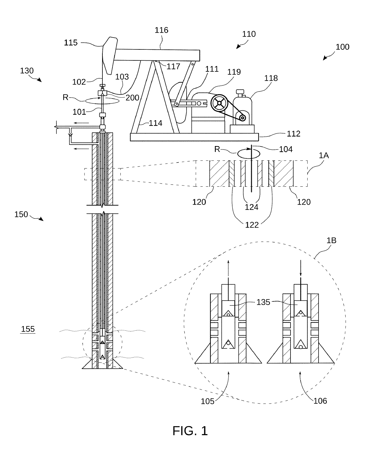
The production of hydrocarbon fluids using a sucker rod pump creates friction and wear as the rods reciprocate up and down within the production tubing.
Such deviations may be in the form of a gentle cork screw created as a largely unavoidable result of forming the wellbore using a rotating drill pipe and bit.
Directional wells are increasingly common and present difficulties when producing via a rod pump.
The presence of wellbore deviations can impart a side-load on the rod-string, resulting in friction and wear at deviation points.
Because the rotation is very slow, it is difficult for the operator to visually observe rotation at the well head.
A failed or otherwise ineffective rod rotator can result in premature failure due to uneven downhole rod or tubing wear.
This condition is known as rod float and can cause the polished rod clamp to briefly lift off the rod rotator table, losing the frictional contact and associated torque imparted on the rods.
Additionally, dynamic conditions such as pump impact or fluid pound can cause the rotator and polished rod to briefly separate and lose the imparted torque.
These conditions are virtually impossible to identify from a brief, on-site observation as they are transient in nature.

Method used


Image

  • Apparatus and Method for Detecting the Rotation of a Rod-String in a Wellbore
  • Apparatus and Method for Detecting the Rotation of a Rod-String in a Wellbore
  • Apparatus and Method for Detecting the Rotation of a Rod-String in a Wellbore

Examples


Embodiment Construction

Definitions

[0055]For purposes of the present application, it will be understood that the term “hydrocarbon” refers to an organic compound that includes primarily, if not exclusively, the elements hydrogen and carbon. Hydrocarbons may also include other elements, such as, but not limited to, halogens, metallic elements, nitrogen, carbon dioxide, and / or sulfuric components such as hydrogen sulfide.

[0056]As used herein, the term “hydrocarbon fluids” refers to a hydrocarbon or mixtures of hydrocarbons that are gases or liquids. For example, hydrocarbon fluids may include a hydrocarbon or mixtures of hydrocarbons that are gases or liquids at formation conditions or at surface condition. Hydrocarbon fluids may include, for example, oil, natural gas, coalbed methane, shale oil, pyrolysis oil, pyrolysis gas, a pyrolysis product of coal, and other hydrocarbons that are in a gaseous or liquid state.

[0057]As used herein, the term “rod-string” includes all components that rotate together relati...


PUM


Abstract

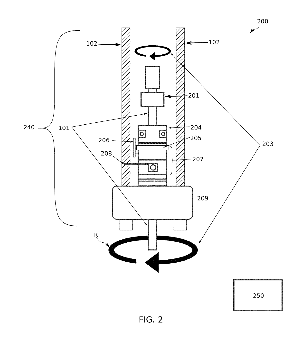
An apparatus for monitoring rod rotation in a rod lift system. The apparatus comprises one or more sensors that reside on the rod string of the rod lift system. The sensor is configured via a processor to generate a signal indicative of radial position of the sensor relative to an external frame of reference. The signal may be sent to a wireless I / O module, with the signals being indicative of at least partial rotation or, alternatively, a lack of rotation, of the rod-string. The processor is configured to generate an alarm if an absence of rod rotation is detected while the rod lift system is running and transmit this signal to the nearby wireless I / O module. A method for monitoring a reciprocating rod lift system is also provided.

Description

CROSS REFERENCE TO RELATED APPLICATIONS[0001]This application claims the benefit of U.S. Ser. No. 62 / 612,503 filed Dec. 31, 2017. That application is entitled “Rod Rotation Detection,” and is incorporated herein in its entirety by reference.STATEMENT REGARDING FEDERALLY SPONSORED RESEARCH OR DEVELOPMENT[0002]Not applicable.THE NAMES OF THE PARTIES TO A JOINT RESEARCH AGREEMENT[0003]Not applicable.BACKGROUND OF THE INVENTION[0004]This section is intended to introduce various aspects of the art, which may be associated with exemplary embodiments of the present disclosure. This discussion is believed to assist in providing a framework to facilitate a better understanding of particular aspects of the present disclosure. Accordingly, it should be understood that this section should be read in this light, and not necessarily as admissions of prior art.Field of the Invention[0005]The present disclosure relates to the field of hydrocarbon recovery operations. More specifically, the present ...

Claims


Application Information

Patent Timeline
IPC IPC(8): E21B47/00F04B47/02E21B43/12G01V3/36G01V3/38G01V3/40
CPCG01V3/36G01V3/38G01V3/40E21B47/0008F04B47/026E21B43/127F04B49/065F04B51/00F04B2207/70E21B47/009
Inventor PHILLIPS, WALTER
Owner PHILLIPS WALTER
Learn More