
Image processing apparatus, image pickup system and moving apparatus

a technology of image processing and moving image, which is applied in the field of image processing apparatus, image pickup system and moving apparatus, can solve the problems of inability to determine the relative merits in advance, the chance of capturing an object which should be imaged may be missed, and the image quality of a moving image captured by this method may not necessarily improve, so as to achieve the effect of easy acquisition of high quality images and minimal blur

Active Publication Date: 2019-06-27
CANON KK
View PDF0 Cites 2 Cited by
  • Summary
  • Abstract
  • Description
  • Claims
  • Application Information

AI Technical Summary

Benefits of technology

The present invention aims to provide a technique to easily capture high quality images with minimal blur. The invention includes an image acquisition system that captures two images using a coded exposure method, an image correction processing unit that generates a third image, and an image comparison unit that evaluates multiple images and selects the highest quality image as the output image. The technical effect of the invention is the ability to easily acquire high quality images with minimal blur.

Problems solved by technology

The relative merits of an image quality between a normal exposure image and a restored image based on a coded exposure image changes depending on the illuminance of the object and the imaging environment, and it is difficult to determine the relative merits in advance.
If an attempt is made to determine the relative merits, many information detection units and an enormous computing volume before imaging are required, and a chance of capturing an object which should be imaged may be missed.
U.S. Pat. No. 8,436,907 discloses a method for increasing the precision of the blur correction processing by performing “coded exposure” and “normal exposure” alternately, but there is no concept that explains the relative merits between these images, and the image quality of a moving image (image) captured by this method does not necessarily improve.

Method used


Image

  • Image processing apparatus, image pickup system and moving apparatus
  • Image processing apparatus, image pickup system and moving apparatus
  • Image processing apparatus, image pickup system and moving apparatus

Examples


embodiment 1

(Image Pickup System)

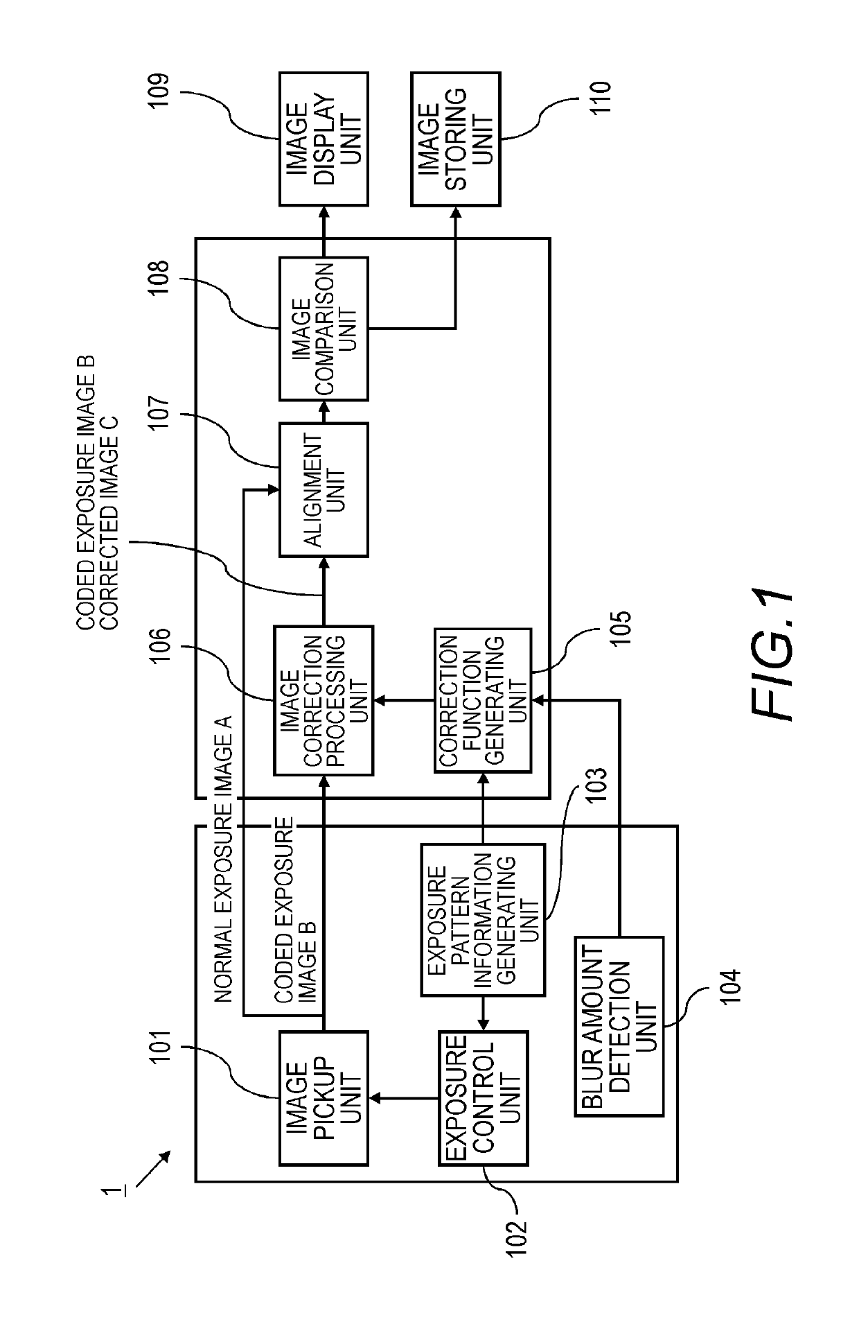
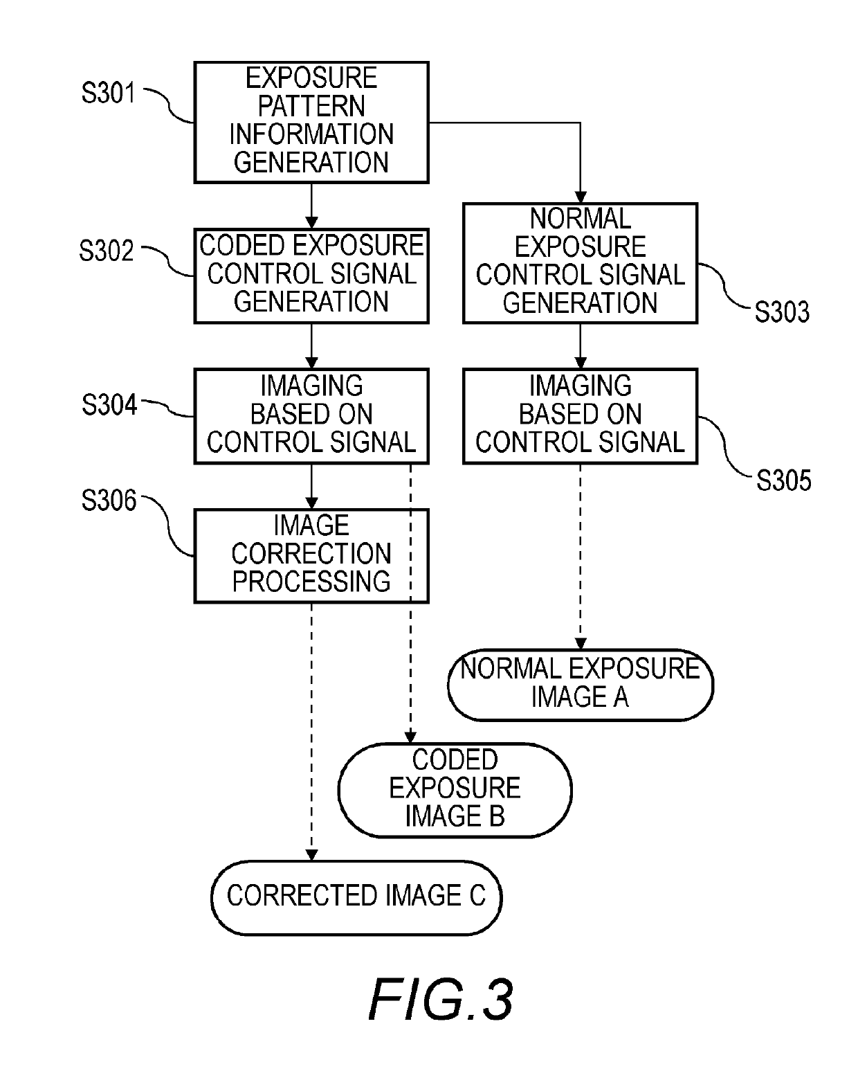
[0022]FIG. 1 is a block diagram depicting a configuration of an image pickup system according to Embodiment 1 of the present invention. The image pickup system 1 includes: an image pickup portion which images an object and acquires a normal exposure image A and a coded exposure image B; an image processing portion which generates an image of which blur is eliminated or reduced, based on the normal exposure image A and the coded exposure image B; and an image output portion which outputs the image. In the configuration example in FIG. 1, the image pickup portion includes an image pickup unit 101, an exposure control unit 102, an exposure pattern information generating unit 103, and a blur amount detection unit 104; and the image processing portion includes a correction function generating unit 105, an image correction processing unit 106, an alignment unit 107 and an image comparison unit 108. For the image output portion, an image display unit 109 which displays...

embodiment 2

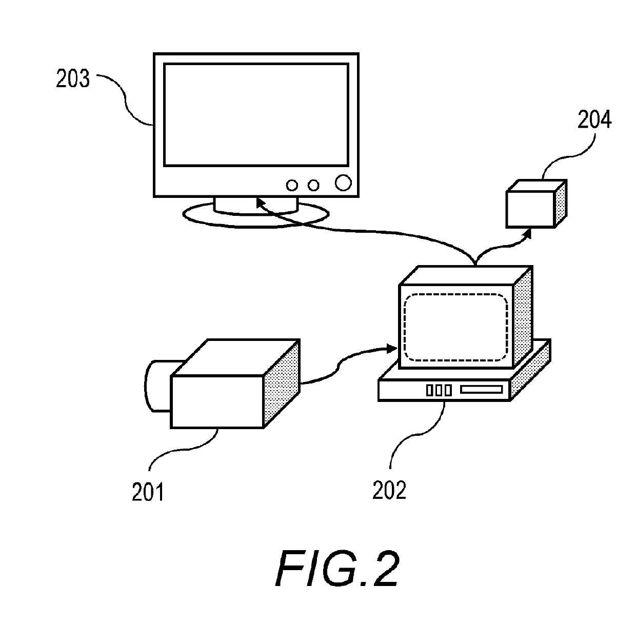
[0063]FIG. 10 shows an illustration depicting a system configuration according to Embodiment 2. In Embodiment 2, an image is inputted to the image processing apparatus 202 by an image storing device 1001, instead of the image pickup device 201. In the image storing device 1001, a normal exposure image A, a coded exposure image B and a corrected image C after the blur correction processing are stored in advance, and these images A, B and C are sent to the image processing apparatus 202 as required. The image storing device 1001 is, for example, a recorder, an image database, an image server, or a storage where image data is stored. The remainder of the configurations and operations of the image processing apparatus 202 (image acquisition processing, blur correction processing, image comparison selection processing) are the same as Embodiment 1.

[0064]By this configuration, a system that is suitable for such an application as a monitoring camera, which requires no processing in real-ti...

embodiment 3

[0065]FIG. 11 shows an illustration depicting a system configuration according to Embodiment 3. Embodiment 3 is an example when the system according to the present invention is installed in a moving apparatus, such as a vehicle 1100. The remainder of the configurations and operations of the image processing apparatus 202 (image acquisition processing, blur correction processing, image comparison selection processing) are the same as Embodiment 1. An image selected or combined by the image comparison unit 108 is stored in the image storing device 204. This image is used for a control unit 1101 of the vehicle 1100 to control the vehicle 1100 (e.g. automatic operation, collision prevention). According to this system, an image with minimal image quality deterioration can be acquired without missing a chance of capturing an object, hence the accuracy of the image used for control can be improved.

Other Embodiments

[0066]The present invention can also be implemented by supplying a program, ...


PUM


Abstract

An image processing apparatus has: an acquisition unit that acquires a first image captured by coded exposure in which a transfer unit is driven for n times, and acquires a second image captured by driving the transfer unit for m times (m<n); an image correction processing unit that generates a third image by performing blur correction processing on the first image; and an image comparison unit that evaluates a plurality of images including at least two of the first image, the second image and the third image, and selects an image of which evaluation is the highest among the plurality of images as an output image, or increases a weight for an image of which evaluation is highest among the plurality of images, relative to those of the other images when an output image is generated by combining the plurality of images.

Description

BACKGROUND OF THE INVENTIONField of the Invention[0001]The present invention relates to a technique to acquire high quality images using coded exposure.Description of the Related Art[0002]As a method for correcting blur of a captured image, a coded exposure method is used. According to the coded exposure method, imaging is performed while temporally coding (modulating) an exposure, and blur correction processing is performed on the acquired coded exposure image, so as to generate a restored image in which blur has been reduced or eliminated. U.S. Pat. No. 8,436,907 discloses a technique to improve the correction accuracy of the coded exposure image based on an image captured by a normal image pickup method when the coded exposure image is acquired.SUMMARY OF THE INVENTION[0003]The relative merits of an image quality between a normal exposure image and a restored image based on a coded exposure image changes depending on the illuminance of the object and the imaging environment, and ...

Claims


Application Information

Patent Timeline
Patent Type & Authority Applications(United States)
IPC IPC(8): H04N5/232G06T7/00
CPCH04N5/23267G06T7/0002G06T2207/30168G06T2207/10144H04N23/81H04N23/683H04N23/73H04N25/771G06T5/73H04N25/532H04N25/53
Inventor SEKINE, HIROSHIKAWABATA, KAZUNARI
Owner CANON KK
Learn More