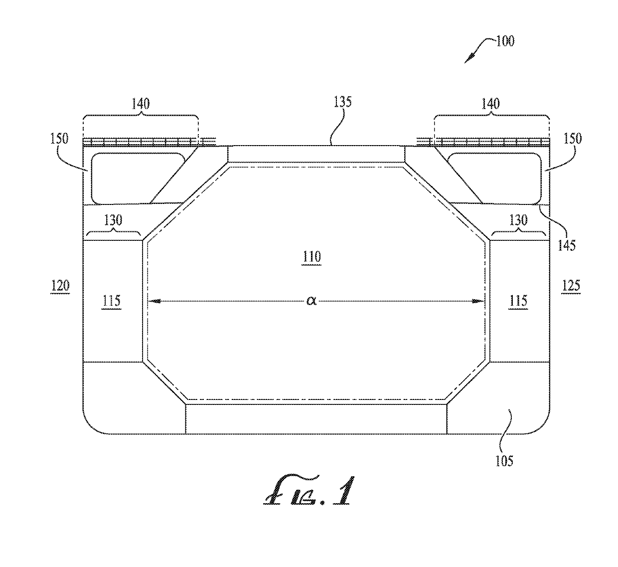
Natural gas liquefaction vessel

a liquefaction vessel and natural gas technology, applied in vessel auxiliary drives, vessel construction, lighting and heating apparatus, etc., can solve the problems of inability to transport gas by pipeline to the location of commercial, loss of gas monetization opportunities, and high cost of land-based liquefaction facilities and gathering pipelines

Inactive Publication Date: 2019-06-27
EXCELERATE LIQUEFACTION SOLUTIONS
View PDF6 Cites 1 Cited by
  • Summary
  • Abstract
  • Description
  • Claims
  • Application Information

AI Technical Summary

Problems solved by technology

However, large quantities of natural gas may sometimes be produced in an area or country where production far exceeds demand, and it may not be feasible to transport the gas by pipeline to the location of commercial demand, for example because the location of production and the location of demand are separated by an ocean or rain forest.
Without an effective way to transport the natural gas to a location where there is a commercial demand, opportunities to monetize the gas may be lost.
Land-based liquefaction facilities and the associated gathering pipelines are costly, may occupy large areas of land and take several years to permit and construct.
Thus, land-based liquefaction facilities are not optimally suited to adapt to variation in the location of natural gas supplies or to liquefy small or stranded gas reserves.
In addition, once natural gas is liquefied at a land based facility, the LNG must be stored in large land-based cryogenic storage tanks, transported through a special cryogenic pipeline to a terminal facility, and then loaded onto a vessel equipped with cryogenic compartments (such a vessel may be referred to as an LNG carrier or “LNGC”), which in combination may increase the overall expense of transporting the gas to its ultimate destination.
LNG projects are inherently capital intensive.
The liquefaction plant is the largest cost component, accounting for approximately 50% of the total cost of the LNG value chain; hence, cost reduction of the liquefaction plant is an important issue.
Of course, development costs are capitalized over the life of the facility.
LNGCs that are available for conversion are typically older ships that lack the necessary space and deadweight for the additional liquefaction equipment.
On these older carriers, ship designers conventionally maximize the cargo tank size due to the ship's original functionality as an LNGC, and therefore cargo space in the hull consumes a large fraction of vessel's deadweight.
A vessel's deadweight is critical to its use, because if the equipment onboard the ship is too heavy, the ship may sit too deeply in the water or break under excessive longitudinal stresses.
Sponsons are sometimes added to the sides of the LNGC to create more cargo space and increase deadweight, but often this does not provide enough deadweight to allow the addition of complex liquefaction equipment.
In addition, old tonnage LNGC vessels are typically steam powered and are not able to generate the required 40-50 MW of power needed for liquefaction equipment.
As a result of these size and power constraints, old tonnage vessels require costly rework to convert them to natural gas liquefaction vessels.
Such rework is especially economically infeasible where the LNGC will be in service for a long duration, such as more than five years, due to the cost of powering the older vessel.
While newbuild vessels may be created using existing LNGC design plans, with the added requirement of natural gas liquefaction, most LNGC plans do not provide the necessary deadweight for the addition of heavy liquefaction equipment.
As is apparent from the aforementioned problems, current old tonnage vessels are not good candidates for conversion to liquefaction-capable LNGCs, as they suffer from the many shortcomings mentioned above, and newbuild vessels designed to maximize cargo space do not have the necessary deadweight for liquefaction equipment.

Method used


Image

  • Natural gas liquefaction vessel
  • Natural gas liquefaction vessel
  • Natural gas liquefaction vessel

Examples


Embodiment Construction

[0020]A natural gas liquefaction vessel is described. In the following exemplary description, numerous specific details are set forth in order to provide a more thorough understanding of embodiments of the invention. It will be apparent, however, to an artisan of ordinary skill that the present invention may be practiced without incorporating all aspects of the specific details described herein. In other instances, specific features, quantities, or measurements well known to those of ordinary skill in the art have not been described in detail so as not to obscure the invention. Readers should note that although examples of the invention are set forth herein, the claims, and the full scope of any equivalents, are what define the metes and bounds of the invention.

[0021]As used in this specification and the appended claims, the singular forms “a”, “an” and “the” include plural referents unless the context clearly dictates otherwise. Thus, for example, reference to a cargo tank includes...


PUM


Abstract

A natural gas liquefaction vessel including an increased deadweight tonnage, as compared to a liquefied natural gas carrier (LNGC) of a comparably-sized ship, is achieved by reducing the LNGC's cargo capacity. This difference creates room on the port and starboard sides of cargo tanks to increase the size of the adjacent wing tanks. The increased size of the wing tanks occupy the space created by the reduced cargo tank size of the vessel and may support a larger upper trunk deck. The ballast wing tanks and smaller cargo tanks increase the deadweight available. With this approach, the larger upper trunk deck of the vessel is able to support an efficient floating liquefaction plant that improves the LNG value chain because it is capable of producing 2.0-3.0 MTPA in the footprint of a standard vessel hull, such as for example a Q-Max hull.

Description

BACKGROUND1. Field of the Invention[0001]Embodiments of the invention described herein pertain to the field of marine liquefaction of natural gas. More particularly, but not by way of limitation, one or more embodiments of the invention describe a natural gas liquefaction vessel.2. Description of the Related Art[0002]Natural gas is typically transported by pipeline from the location where it is produced to the location where it is consumed. However, large quantities of natural gas may sometimes be produced in an area or country where production far exceeds demand, and it may not be feasible to transport the gas by pipeline to the location of commercial demand, for example because the location of production and the location of demand are separated by an ocean or rain forest. Without an effective way to transport the natural gas to a location where there is a commercial demand, opportunities to monetize the gas may be lost.[0003]Liquefaction of natural gas facilitates storage and tran...

Claims


Application Information

Patent Timeline
Patent Type & Authority Applications(United States)
IPC IPC(8): B63B25/08B63B25/16B63J2/14F25J1/00F25J1/02
CPCB63B25/08B63B25/16B63J2/14F25J1/0022F25J1/0277F25J1/0259B63B2025/087F25J2220/60F25J1/0278B63B3/48B63B3/52B63B3/70B63B11/02B63B2035/448B63J3/02F25J2290/72
Inventor CARROLL, MICHAEL TODDTROTTER, GRAEME DAVIDWILKINSON, TREVOR EARLMCGEACHIE, KENNETH HUGH
Owner EXCELERATE LIQUEFACTION SOLUTIONS
Why Eureka
Try Eureka