Vehicle control apparatus and vehicle control system

a technology of vehicle control and control apparatus, which is applied in the direction of process and machine control, transportation and packaging, instruments, etc., can solve the problems of easy deterioration of fuel efficiency or electricity efficiency of the vehicle, increased transportation cost of the cargo, and etc., to achieve easy deterioration of fuel efficiency and/or electricity efficiency, easy to affect quality, and increase the possibility of transportation

Inactive Publication Date: 2019-06-27
TOYOTA JIDOSHA KK +1
View PDF0 Cites 4 Cited by
  • Summary
  • Abstract
  • Description
  • Claims
  • Application Information

AI Technical Summary

Benefits of technology

[0004]In recent years, the types of cargoes, which are dealt with by the cargo transport vehicle, are progressively diversified on account of the widespread use of the mail order service based on the use of the internet. Therefore, it is estimated that the opportunities of the transport will be progressively increased not only for the cargoes such as clothing, food, books or the like for which the vibration of the vehicle hardly affects the quality but also for the cargoes such as precision machines, electronic equipment, glass products or the like for which the vibration of the vehicle easily affects the quality.

Problems solved by technology

The fuel efficiency or the electricity efficiency of the vehicle is easily deteriorated.
If the fuel efficiency or the electricity efficiency of the vehicle is deteriorated for the reason as described above, then the cruising distance of the vehicle is shortened, and thus it is feared that the transport cost of the cargo may be raised.
Therefore, it is possible to raise the transport quality of the cargo, while there is a possibility that the deterioration of the fuel efficiency and / or the electricity efficiency may be caused.
Therefore, there is a possibility that the transport cost of the cargo may be increased.
Further, for example, the magnitude of the vibration generated in the cargo loading space of the vehicle is not necessarily uniform in the entire region of the space.
However, if the number of cargoes is increased, and / or if the size of the cargo is increased, then there is a possibility that it may be difficult to arrange all of the cargoes at the low vibration position as described above.

Method used


Image

  • Vehicle control apparatus and vehicle control system
  • Vehicle control apparatus and vehicle control system
  • Vehicle control apparatus and vehicle control system

Examples


first embodiment

[0031]At first, a first embodiment of the present disclosure will be explained on the basis of FIGS. 1 to 7. In this section, an example will be described, in which the present disclosure is applied to vehicles as moving bodies in a moving body system including a plurality of moving bodes capable of performing the autonomous traveling.

(System Outline)

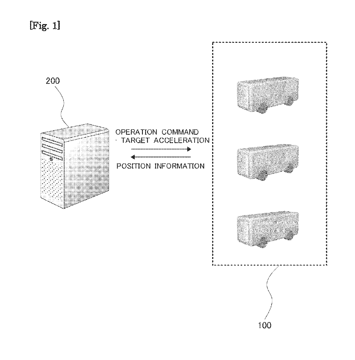
[0032]FIG. 1 indicates an outline of a moving body system according to this embodiment. The moving body system indicaten in FIG. 1 is configured to include a plurality of autonomous traveling vehicles 100 which perform the autonomous traveling in accordance with provided operation commands, and a server apparatus 200 which issues the operation commands to the respective autonomous traveling vehicles 100. The autonomous traveling vehicle 100 is an automatic driving vehicle which provides predetermined service. On the other hand, the server apparatus 200 is an apparatus which manages the plurality of autonomous traveling vehicles 100.

[003...

second embodiment

[0082]Next, a second embodiment of the present disclosure will be explained on the basis of FIGS. 8 and 9. In this section, constitutive components, which are different from those of the first embodiment described above, will be explained, and the same or equivalent constitutive components are omitted from the explanation. In the first embodiment described above, the case has been described, in which one cargo is loaded on one autonomous traveling vehicle 100. However, in this embodiment, an explanation will be made about a case in which a plurality of cargoes are loaded on one autonomous traveling vehicle 100.

[0083]Assuming that the autonomous traveling vehicle 100 is effectively utilized as the cargo transport vehicle, it is effective to transport a plurality of cargoes by way of one autonomous traveling vehicle 100. In such a situation, it is desirable that the cargoes, which are loaded on each of the autonomous traveling vehicles 100, are managed on the side of the server appara...

modified embodiment of second embodiment

[0100]For example, the magnitude of the vibration generated in the cargo loading space of the autonomous traveling vehicle 100 is not necessarily uniform in the entire region of the space. FIG. 10 schematically indicates an example of the cargo loading space of the autonomous traveling vehicle 100. In the example shown in FIG. 10, the shaking width easily increases when the roll vibration and / or the pitch vibration is / are generated in relation to the cargo C2 which is stacked on another cargo, as compared with the cargo C1 which is directly arranged on the surface of the floor FL of the cargo loading space CS. Further, the shaking width easily increases when the heave vibration and / or the pitch vibration is / are generated in relation to the cargo C3 which is arranged on the overhang portion OHf disposed frontwardly from the axle of the front wheel WHf, of the surface of the floor FL and the cargo C4 which is arranged on the overhang portion OHr disposed backwardly from the axle of th...


PUM


Abstract

The present disclosure realizes the transport quality and the transport cost corresponding to, for example, the type of a cargo transported by a vehicle. The present disclosure resides in a vehicle control apparatus for attenuating the vibration of the vehicle by adjusting a parameter that affects a predetermined acceleration so that the predetermined acceleration, which includes at least one of an acceleration in an upward-downward direction of the vehicle, an acceleration in a lateral direction of the vehicle, and an acceleration in a front-back direction of the vehicle, approaches a target acceleration, wherein a required vibration suppression level of the cargo transported by the vehicle is acquired, and the target acceleration is set on the basis of the acquired required vibration suppression level. Then, the control apparatus adjusts the parameter that affects the predetermined acceleration on the basis of the set target acceleration.

Description

CROSS REFERENCE TO RELATED APPLICATIONS[0001]This application claims the benefit of Japanese Patent Application No. 2017-252411, filed on Dec. 27, 2017, which is hereby incorporated by reference herein in its entirety.BACKGROUNDTechnical Field[0002]The present disclosure relates to a vehicle control apparatus for a vehicle for transporting a cargo. In particular, the present disclosure relates to a technique for attenuating the vibration of the vehicle.Description of the Related Art[0003]In relation to the vehicle such as an automobile or the like, such a technique is known that the vibration of the vehicle is attenuated and thus the damping or vibration suppression performance of the vehicle is improved by adjusting the parameter which affects the predetermined acceleration including at least one of the acceleration in the upward-downward direction of the vehicle, the acceleration in the lateral direction of the vehicle, and the acceleration in the front-back direction of the vehic...

Claims


Application Information

Patent Timeline
Patent Type & Authority Applications(United States)
IPC IPC(8): B60W30/02B60W10/04B60W10/22
CPCG05D2201/0213B60G17/0164B60G17/0155B60G2202/152B60G2500/10B60W30/02B60W10/04B60W10/22B60W2300/12B60W2400/00B60W2710/226B60W2720/106G05D1/0088B60G17/015B60G17/08B60G2400/102B60G2400/106B60G2600/0422B60G2800/162B60G2600/71B60W2720/125B60W2720/00B60W30/16B60W30/10B60W30/182B60W60/0013B60K28/08B60G2400/104
Inventor YAMAMURO, NAOKIADACHI, SHINICHIHATTORI, RYOAMAKASU, TAICHIHIRUMA, KEIGO
Owner TOYOTA JIDOSHA KK
Why Eureka
Try Eureka