
Temporary Aortic Occlusion Device

a technology of aortic valve and occlusion device, which is applied in the field of temporary aortic valve occlusion device, can solve the problems of traumatic hemorrhage, death of active-duty military service members, and difficulty in non-compressible torso hemorrhag

Active Publication Date: 2019-06-27
MICROVENTION INC +2
View PDF0 Cites 4 Cited by
  • Summary
  • Abstract
  • Description
  • Claims
  • Application Information

AI Technical Summary

Benefits of technology

The present invention is a device used to temporarily block the blood flow in a patient's aorta. It has a part that helps the user determine if the device is positioned correctly, and a part that is expanded to completely block the blood flow. The device is designed to be easy to use and will provide little resistance when positioned in the patient's aorta.

Problems solved by technology

Traumatic hemorrhage, primarily the result of blast injuries, is the leading cause of death in active-duty military service members.
Although the widespread use of tourniquets has helped to reduce loss of life from severe lower extremity injury, non-compressible torso hemorrhage remains a challenge with high mortality given the relative anatomic inaccessibility of this region to obtain hemorrhage control.
Pelvic bleeding, in particular, can be severe and difficult to control, requiring advanced, upper echelon hospital-based care, such as angioembolization, for definitive treatment.
Because these advanced care methods and specially trained operators are at higher levels of care, mortality remains high.
Unfortunately, outside of pelvic binders for pelvic fracture stabilization, which have limited success in hemorrhage control and are of no value in penetrating trauma there, has been little advancement in the control of non-compressible torso bleeding at the lower echelons of care.
Traditionally, early temporary control for non-compressible torso hemorrhage has been limited to thoracotomy with aortic cross-clamping.
This technique has been reserved for moribund patients with absent or lost pulses and has an associated high morbidity and mortality.
Placement of a temporary occlusion balloon in the aorta is performed under sterile conditions using ultrasound and fluoroscopic guidance, which requires time, skill, and bulky portable x-ray machines.
Despite the potentially life-saving nature of aortic balloon occlusion in the setting of massive torso and / or pelvic hemorrhage, current approaches for the placement these devices require fluoroscopic guidance.
Additionally, due to the size of the currently available device surgery is required to repair the arteriotomy created by the catheter.
Earlier availability of this technique could allow first-responders to stabilize non-compressible torso bleeding until advanced care was available resulting in decreased mortality.

Method used


Image

  • Temporary Aortic Occlusion Device
  • Temporary Aortic Occlusion Device
  • Temporary Aortic Occlusion Device

Examples


Embodiment Construction

[0041]Specific embodiments of the invention will now be described with reference to the accompanying drawings. This invention may, however, be embodied in many different forms and should not be construed as limited to the embodiments set forth herein; rather, these embodiments are provided so that this disclosure will be thorough and complete, and will fully convey the scope of the invention to those skilled in the art. The terminology used in the detailed description of the embodiments illustrated in the accompanying drawings is not intended to be limiting of the invention. In the drawings, like numbers refer to like elements.

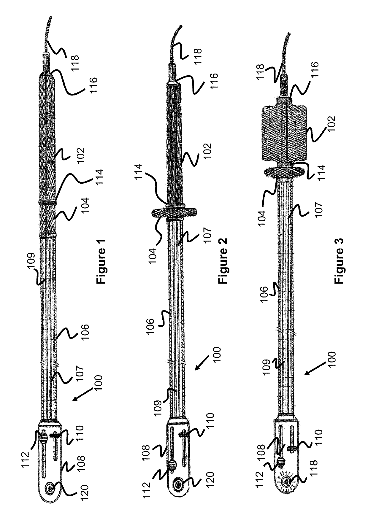
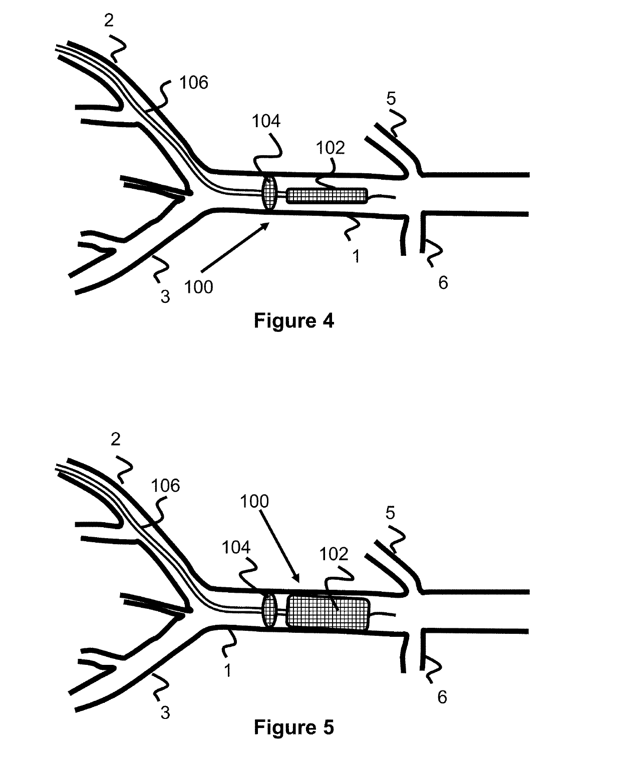
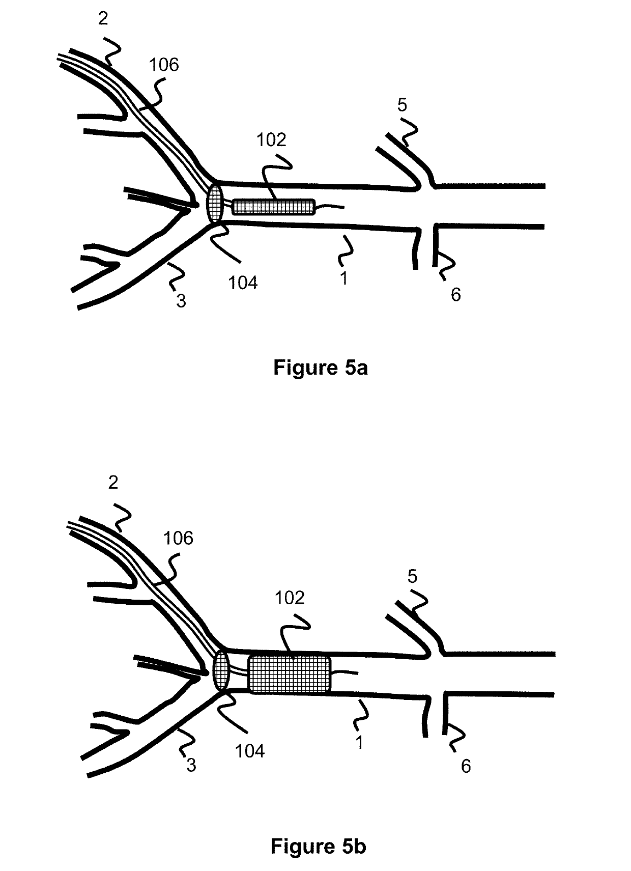
[0042]FIGS. 1-5 are directed to a temporary aortic occlusion device 100 that has a radially expandable mesh locator 104 and a radially expandable mesh occlusion portion 102. The device 100 can be loaded in a femoral sheath (e.g., 6F Sheath) and advanced into the common iliac towards the aortic bifurcation target. Once the distal end of the device 100 is close ...


PUM


Abstract

A temporary aortic occlusion device is disclosed, having an expandable locator portion and an expandable occlusion portion. The expandable locator portion assists a user in determining whether the distal end of the device has been advanced within a patient's aorta, and the occlusion portion is expanded to occlude the patient's aorta, preferably below the renal arteries.

Description

RELATED APPLICATIONS[0001]This application is a continuation-in-part of U.S. patent application Ser. No. 15 / 690,152 filed Aug. 29, 2017 entitled Temporary Aortic Occlusion Device, which claims priority to and benefit of U.S. Provisional Application Ser. No. 62 / 382,705 filed Sep. 1, 2016 entitled Temporary Aortic Occlusion Device, both of which are hereby incorporated herein by reference in their entireties.BACKGROUND OF THE INVENTION[0002]This application relates to a temporary aortic occlusion device for controlling torso hemorrhage.[0003]Traumatic hemorrhage, primarily the result of blast injuries, is the leading cause of death in active-duty military service members. Although the widespread use of tourniquets has helped to reduce loss of life from severe lower extremity injury, non-compressible torso hemorrhage remains a challenge with high mortality given the relative anatomic inaccessibility of this region to obtain hemorrhage control.[0004]Reports have suggested that up to 25%...

Claims


Application Information

Patent Timeline
IPC IPC(8): A61B17/12
CPCA61B17/12109A61B17/1204A61B17/12136A61B17/1214A61B2017/1205A61B2090/0807A61B17/12172A61B17/12177A61B2017/00942
Inventor GREENE, JR., GEORGE R.SEPETKA, IVANLEI, CATHYNGUYEN, RUPALBRADLEY, MATTHEW J.AHLERS, STEPHEN T.GOFORTH, CARL W.STONE, JAMES R.
Owner MICROVENTION INC
Learn More