
Spread spectrum clock generation apparatus and method, and display device and touch display device

Active Publication Date: 2019-06-06
LG DISPLAY CO LTD
View PDF6 Cites 12 Cited by
  • Summary
  • Abstract
  • Description
  • Claims
  • Application Information

AI Technical Summary

Benefits of technology

The present disclosure aims to provide a spread spectrum clock generation apparatus and method, as well as a display device and touch display device that can reduce electromagnetic interference (EMI). This can occur during data transmission without increasing the capacity of a buffer memory or increasing jitter (the time delay of a signal). Another aspect is reducing EMI without increasing the capacity of the data reception-side buffer memory. Overall, the invention provides a solution for reducing EMI and improving the performance of electronic devices.

Problems solved by technology

However, a high-frequency clock signal which is a regularly generated may cause Electro-Magnetic Interference (EMI).
EMI may cuase malfunctions of nearby circuits and devices.
In addition, the trend in which the plane display devices have larger sizes, causes the length of a line path within a display device to become longer and requires a short rising transition time or a short falling transition time, and thus may cause the radiation of a larger amount of electromagnetic waves.
Among them, the Hershey-Kiss modulation profile is advantageous in that the power density of a modulated clock signal appears to be relatively uniform, but disadvantageous in that a configuration of the Hershey-Kiss modulation profile is complex.
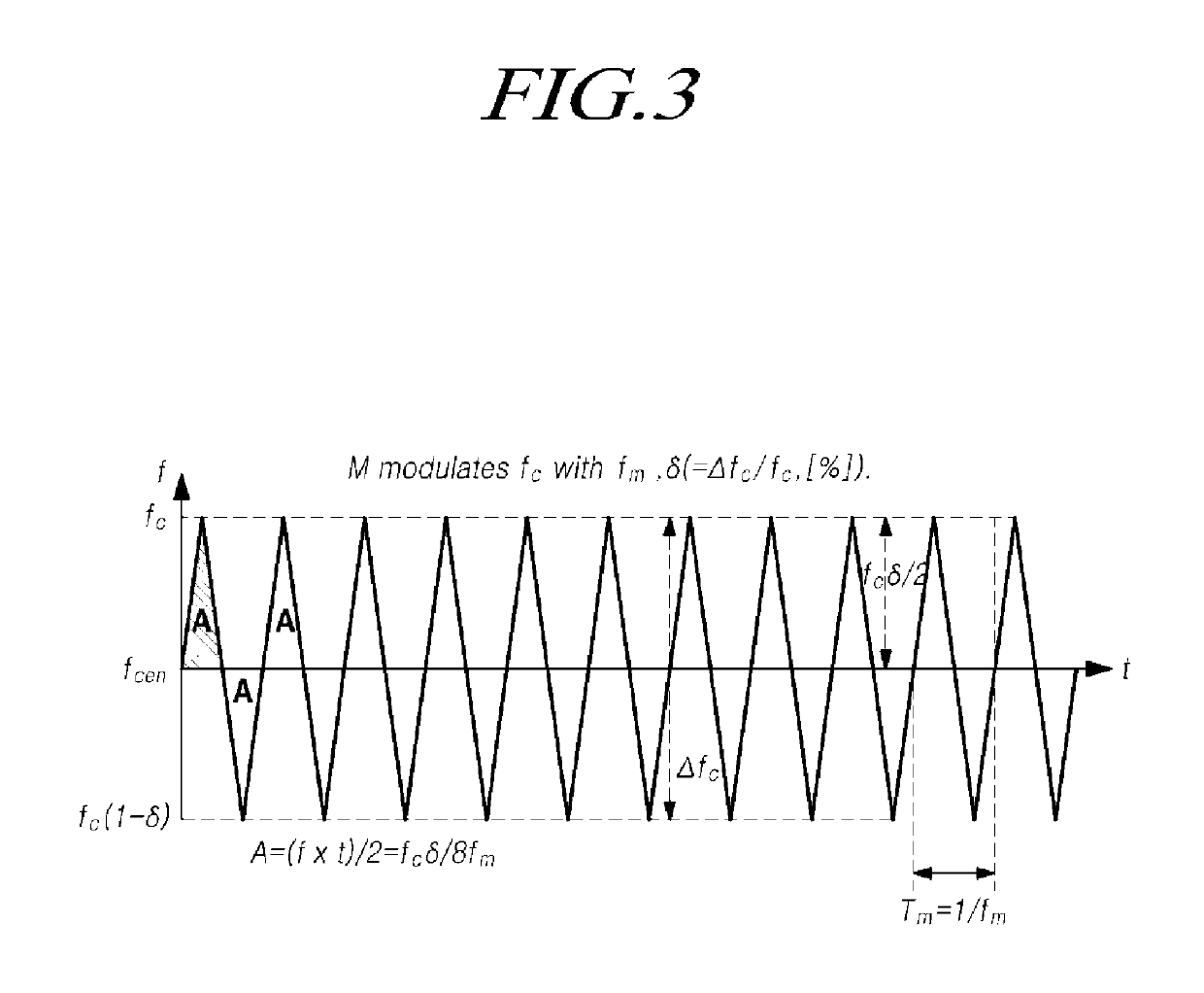
In contrast, each of the sine wave modulation profile and the triangle modulation profile are disadvantageous in that a power density for each frequency at the maximum spread frequency of a modulated clock signal appears to be greater than the average power density value.

Method used


Image

  • Spread spectrum clock generation apparatus and method, and display device and touch display device
  • Spread spectrum clock generation apparatus and method, and display device and touch display device
  • Spread spectrum clock generation apparatus and method, and display device and touch display device

Examples


Embodiment Construction

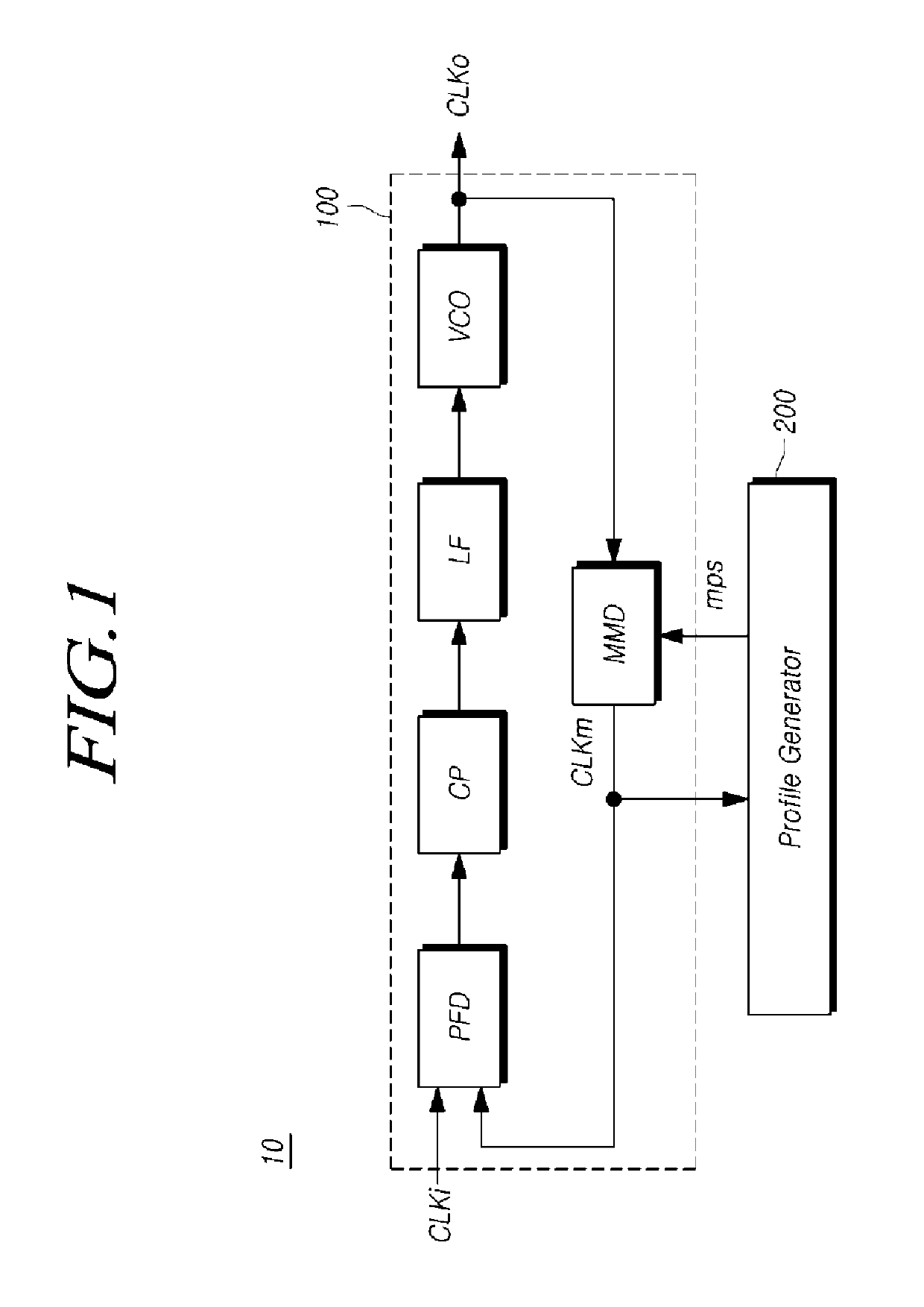
[0055]Hereinafter, exemplary aspects of the present disclosure will be described in detail with reference to the accompanying drawings. In assigning reference numerals to elements in the drawings, the same reference numerals will designate the same elements where possible although they are shown in different drawings. Also, in the following description of the present disclosure, a detailed description of known functions and configurations incorporated herein will be omitted when it may make the subject matter of the present disclosure rather unclear.

[0056]In addition, such terms as “first”, “second”, “A”, “B”, “(a)”, “(b)”, and the like, may be used herein when describing elements of the present disclosure. These terms are merely used to distinguish one element from other elements, and the essence of a corresponding element, an order thereof, a sequence thereof, or the number of the corresponding elements are not limited by the terms. When an element is described as being “connected...


PUM


Abstract

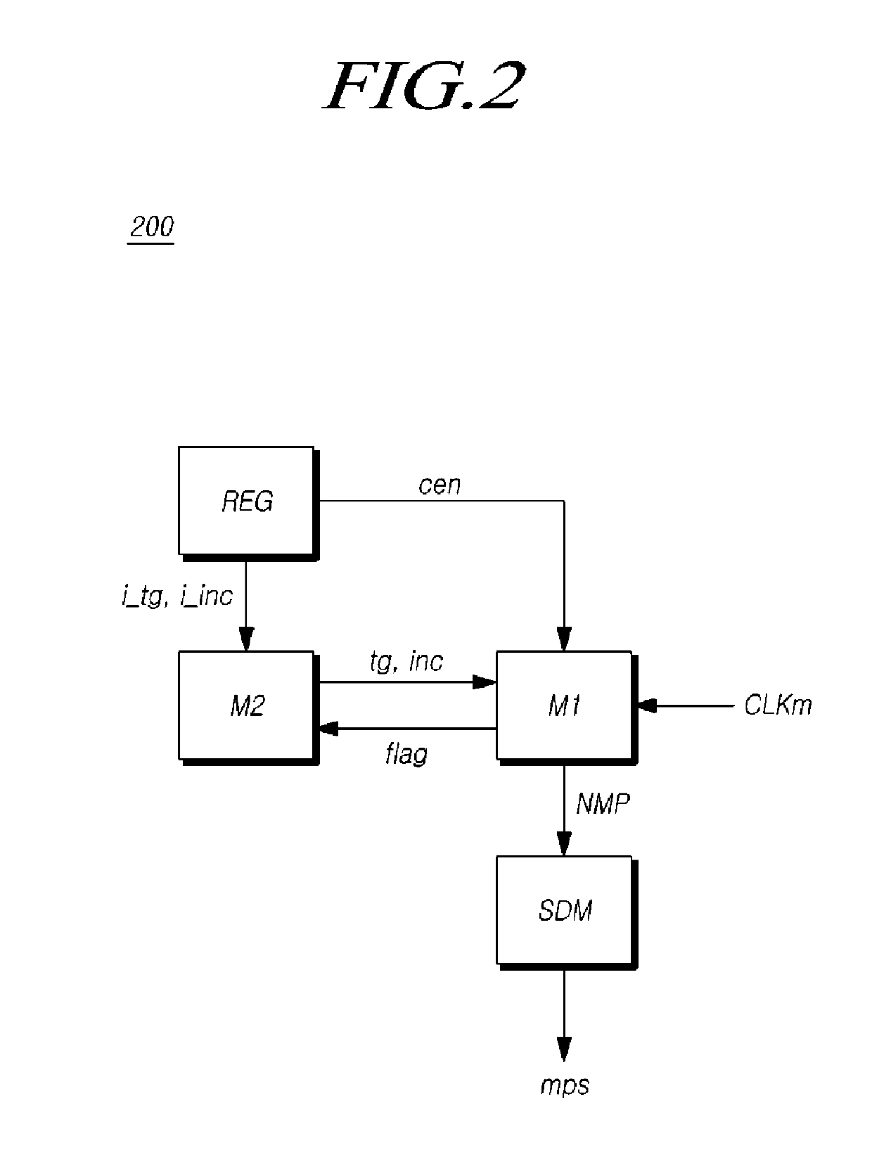
A spread spectrum clock generation apparatus includes a frequency modulator configured to generate an output clock signal, a frequency of which is variable with reference to a predetermined center frequency, by frequency-modulating an input clock signal according to a modulation profile signal; and a profile generator configured to generate a nested-modulation profile for controlling the frequency of the output clock signal, generate the modulation profile signal according to the nested-modulation profile, and output the modulation profile signal to the frequency modulator, wherein the profile generator is further configured to generate the nested-modulation profile by varying a cycle and a change range of a triangle modulation profile having a triangle waveform pattern having a pre-designated cycle and a pre-designated amplitude with reference to the center frequency in a time-frequency domain.

Description

CROSS REFERENCE TO RELATED APPLICATION[0001]This application claims priority from Korean Patent Application No. 10-2017-0167055, filed on Dec. 6, 2017, which is hereby incorporated by reference in its entirety for all purposes as if fully set forth herein.BACKGROUNDField of the Disclosure[0002]The present disclosure relates to a spread spectrum clock generation apparatus and a spread spectrum clock generation method, and a display device and a touch display device using the same.Description of the Background[0003]With the advancement of the information-oriented society and required technology, the amount of data that various electronic devices need to process has rapidly increased, and thus, the operation speeds of various electronic devices have become higher.[0004]A rise in the speed of electronic devices according to an increase in the amount of data not only signifies a rise in the rate at which data is transmitted / received between the electronic devices, but also signifies a ri...

Claims


Application Information

Patent Timeline
IPC IPC(8): H03K3/013H03L7/08H03L7/107G06F3/044G09G3/3225G09G3/36
CPCH03K3/013H03L7/0802H03L7/1075H03L7/1072G06F3/044G09G3/3225G09G3/3648G09G2310/0264G06F1/08H03L7/197G06F3/0418G06F3/04184G09G2330/06G09G2310/08G09G3/2096G09G5/008G09G2354/00H03L7/1976H04B1/69H03C3/0925H03L7/08G06F1/04G06F3/04164
Inventor JUN, JAEHUNPARK, HYUNKYU
Owner LG DISPLAY CO LTD
Learn More