Hybrid lidar system

a lidar and hybrid technology, applied in the field of sensor systems, can solve the problems of limited high-speed flash-based lidar sensor, difficult point to point correlation, and limited gimbal-based scanning with array sensor,

Active Publication Date: 2019-06-06
THE BF GOODRICH CO
View PDF0 Cites 0 Cited by
  • Summary
  • Abstract
  • Description
  • Claims
  • Application Information

AI Technical Summary

Benefits of technology

[0007]A hybrid LIDAR system includes a platform. A flash-based LIDAR detector array is mounted to the platform. A broad laser emitter is mounted to the platform and is operatively connected to the LIDAR detector array for flash-based LIDAR sensing. A first Risley prism pair is mounted to the platform and is optically coupled to the broad laser emitter for scanning a scene with a broad beam from the broad laser emitter. A second Risley prism pair is mounted to the platform and is optically coupled to the LIDAR detector array for directing returns of the broad beam from the scene to the LIDAR detector

Problems solved by technology

Scanning point LIDAR systems can have a better FOV but have difficulty with point to point correlation due to limits of geo-registration systems.
Gimbal-based scanning with an array sensor i

Method used


Image

  • Hybrid lidar system

Examples


Embodiment Construction

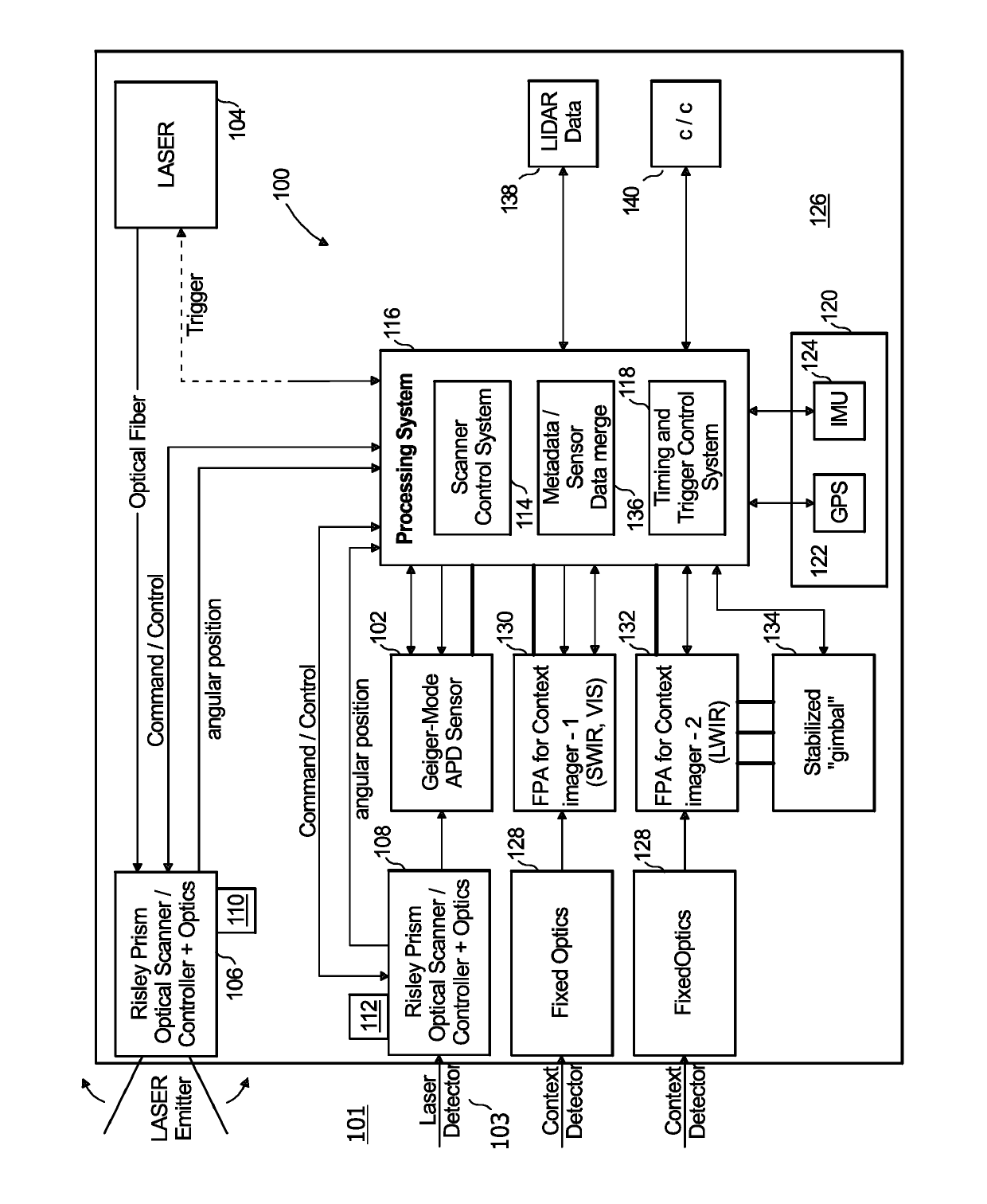
[0014]Reference will now be made to the drawings wherein like reference numerals identify similar structural features or aspects of the subject disclosure. For purposes of explanation and illustration, and not limitation, a partial view of an exemplary embodiment of a system in accordance with the disclosure is shown in FIG. 1 and is designated generally by reference character 100. The systems and methods described herein can be used to generate geo-registered points which can be combined into a point cloud, e.g., for use in operating aircraft including unmanned air vehicles, piloted vehicles, and optionally piloted vehicles.

[0015]A hybrid LIDAR system 100 includes a flash-based LIDAR detector array 102, e.g., a Geiger-mode APD sensor. A broad laser emitter 104 is operatively connected to the LIDAR detector array 102 for flash-based LIDAR sensing. A first beam steering mechanism 106 is operatively connected with the broad laser emitter 104, e.g., by an optical fiber, for scanning a ...


PUM


Abstract

A hybrid LIDAR system 100 includes a flash-based LIDAR detector array. A broad laser emitter is operatively connected to the LIDAR detector array for flash-based LIDAR sensing. A first beam steering mechanism is operatively connected with the broad laser emitter for scanning a scene with a broad beam from the broad laser emitter. A second beam steering mechanism is operatively connected with the LIDAR detector array for directing returns of the broad beam from the scene to the LIDAR detector array.

Description

BACKGROUND OF THE INVENTION1. Field of the Invention[0001]The present disclosure relates to sensor systems, and more particularly to LIDAR / LADAR systems.2. Description of Related Art[0002]Traditional flash-based (array) LIDAR has a fixed field-of-view (FOV). Scanning point LIDAR systems can have a better FOV but have difficulty with point to point correlation due to limits of geo-registration systems. Gimbal-based scanning with an array sensor is restricted to slow scans due to the mass of the sensor. This limits a flash-based LIDAR sensor's utility for high speed, high FOV operations such as required by collision avoidance systems.[0003]The conventional techniques have been considered satisfactory for their intended purpose. However, there is an ever present need for improved sensor systems. This disclosure provides a solution for this need.SUMMARY OF THE INVENTION[0004]A hybrid LIDAR system 100 includes a flash-based LIDAR detector array. A broad laser emitter is operatively conne...

Claims


Application Information

Patent Timeline
IPC IPC(8): G02B26/08G01S7/486G02B26/10G01S7/481G01S17/10G06T7/30G01S7/4865
CPCG02B26/0883G01S7/4865G02B26/108G01S7/4817G01S17/10G06T7/30G01S17/42G01S7/4816
Inventor RAMSEY, SCOTT W.JAROK, JONATHAN C.JOHNSON, JAMES B.
Owner THE BF GOODRICH CO
Why Eureka
Try Eureka