
Microscope illumination device and adapter therefor

Active Publication Date: 2005-10-27
AUBURN UNIV
View PDF51 Cites 61 Cited by
  • Summary
  • Abstract
  • Description
  • Claims
  • Application Information

AI Technical Summary

Benefits of technology

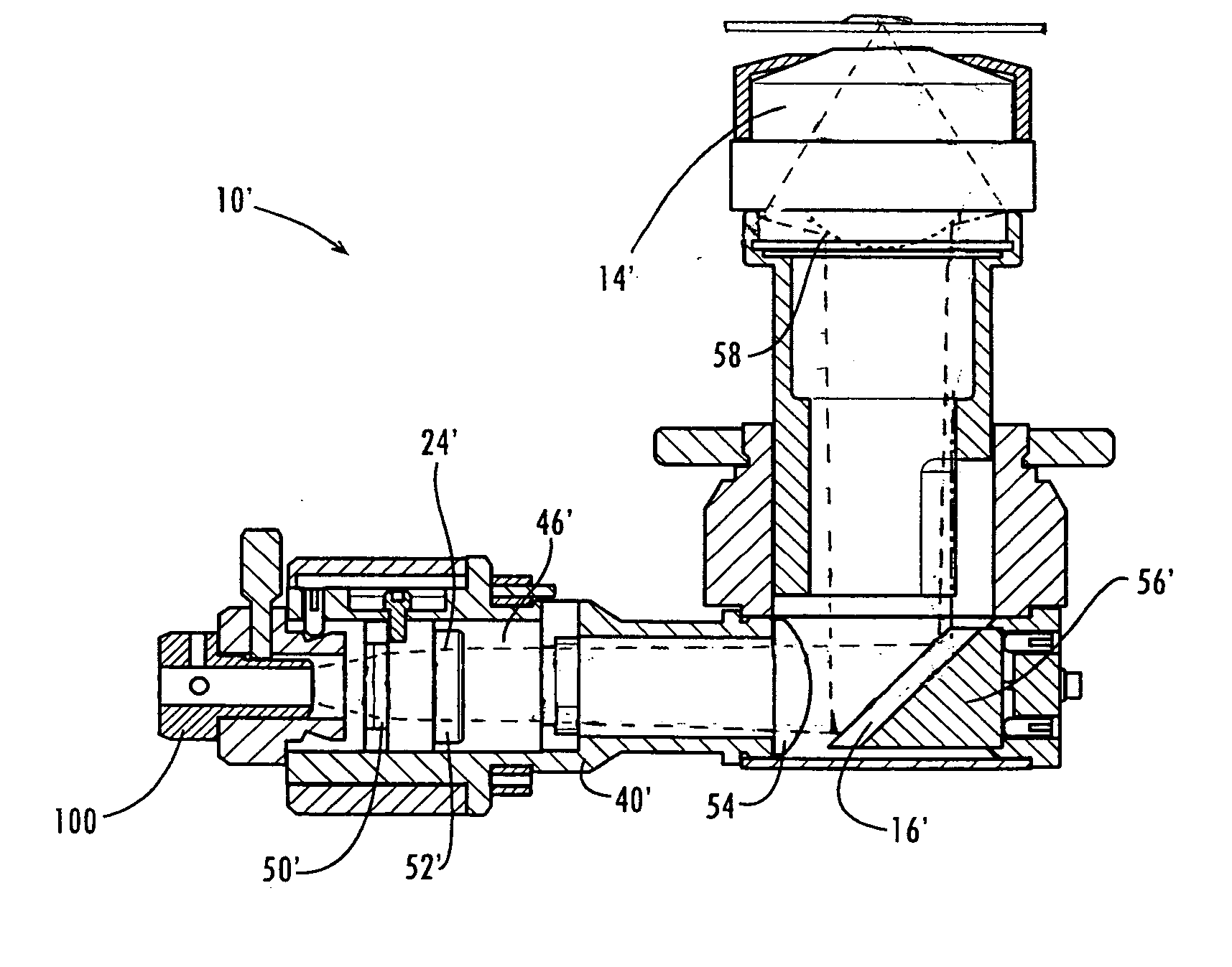
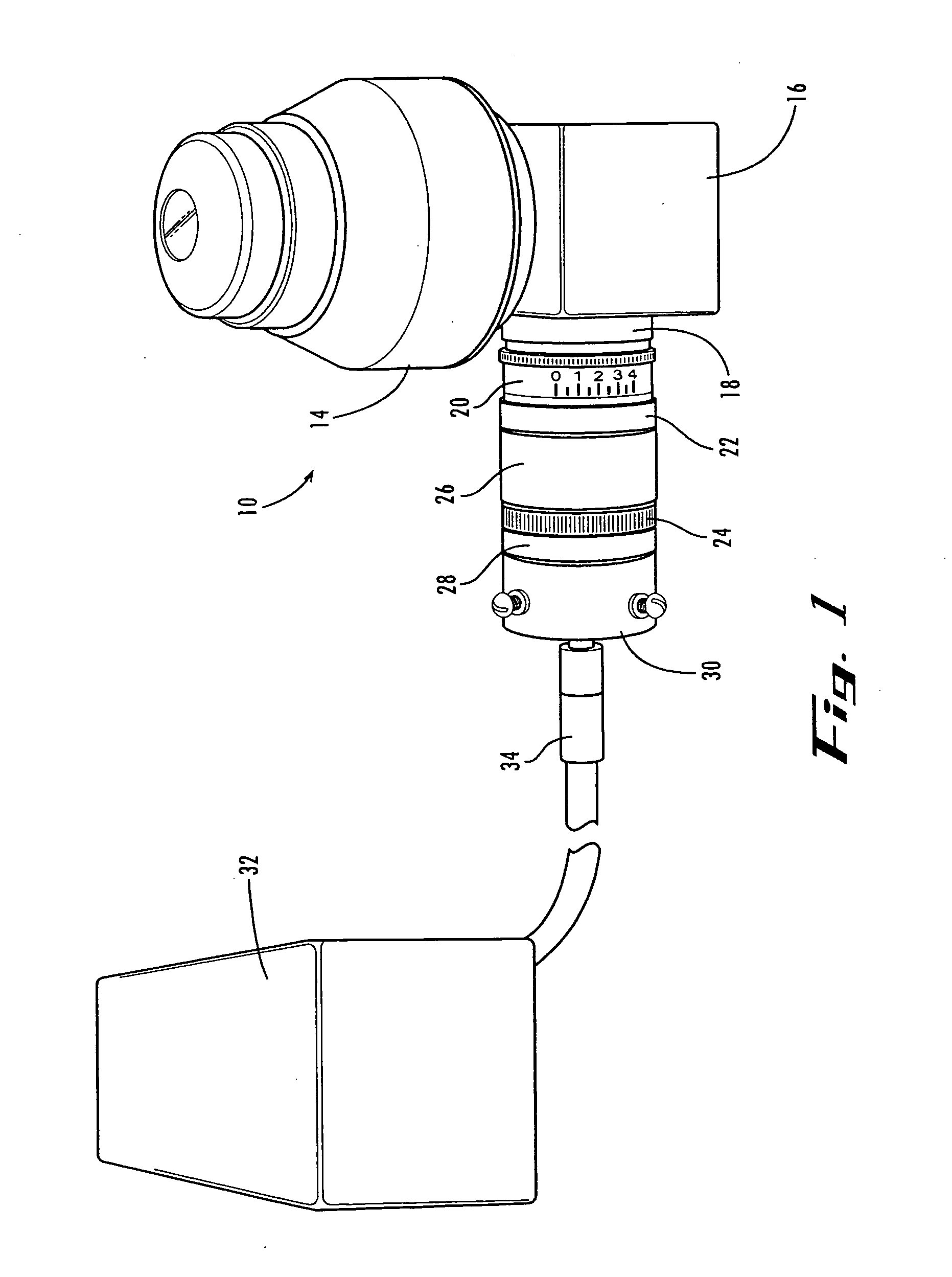
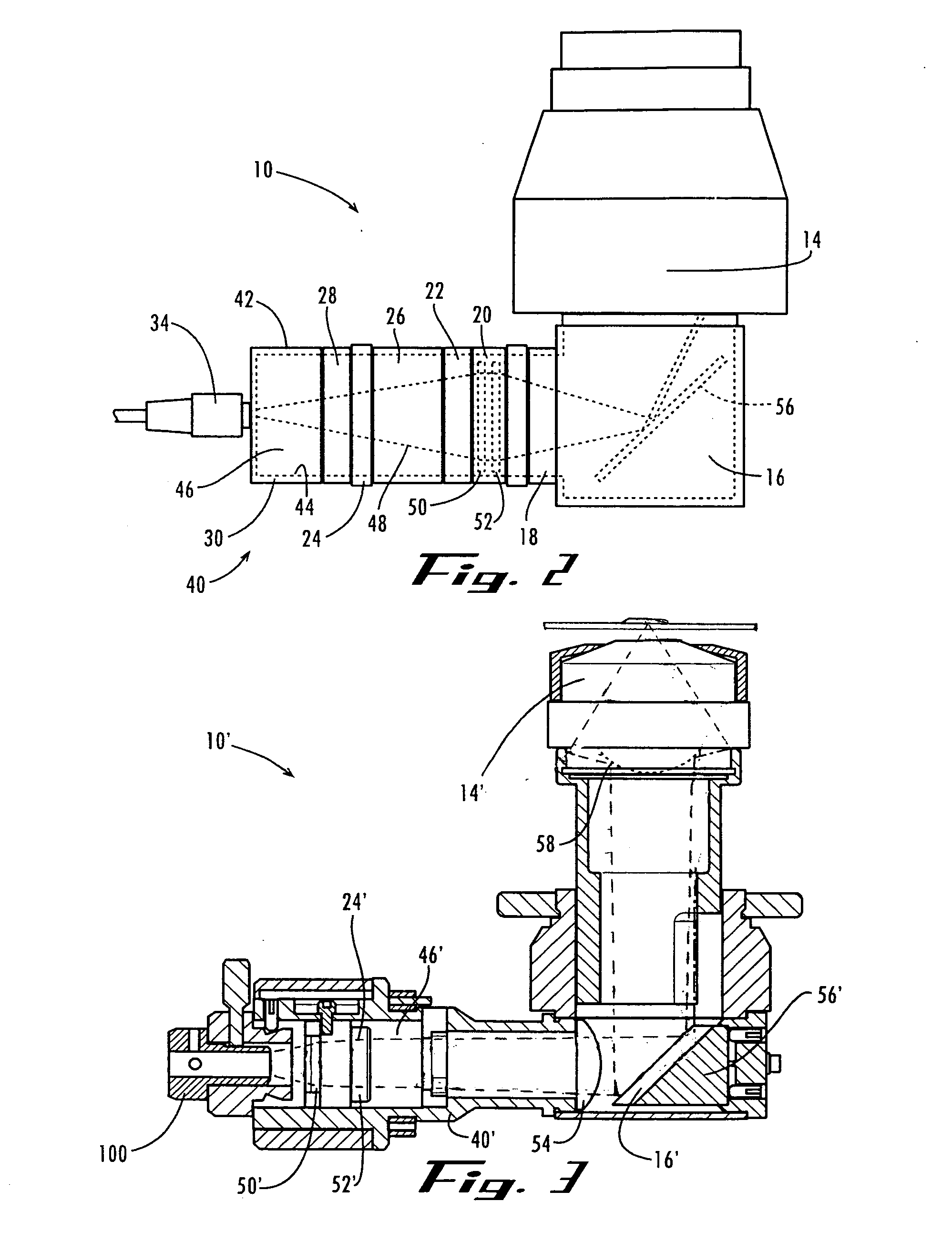
[0034] In its various forms, the present invention provides an improved illumination system for a microscope, providing superior resolution and image contrast, and very efficient usage of light for sample illumination. In an example form of the invention, the illumination system includes an illumination device having a light source coupled to a darkfield condenser, for focusing a hollow cone of light onto a specimen under observation. The invention also includes an adapter for enhancing the economy of light transmission to the specimen. The components of the illumination device are preferably housed in an integral housing and / or are substantially rigidly coupled to one another to maintain alignment and facilitate efficient setup and use. The system and method of the present invention are particularly well suited for adaptation to fluorescence microscopy techniques.
[0040] In yet another aspect, the invention is a illumination device for a microscope having at least one light source for generating light to illuminate a sample for microscopic observation, at least one collimating lens for collimating light generated by the light source, a darkfield condenser for receiving collimated light and directing a hollow cone of light onto the sample under observation, and an adapter for enhancing efficiency of light transmission from the light source to the darkfield condenser.
[0045] In yet another aspect, the invention is a method of reducing photobleaching in a sample under illumination, which includes selective excitation of fluorescence in the sample.
[0046] In yet another aspect, the invention is a method of improving microscopy resolution. The method includes observing a sample under illumination by light directed through a high aperture condenser to generate total internal reflection.

Problems solved by technology

The challenge in microscopy today is not only the enhancement of finer and finer resolution, but also the development of techniques for observing biochemical events in real time, as they happen, without destroying the biological specimen in the process.
The ultraviolet microscope offers finer resolution and better magnification than an ordinary light microscope, but it has serious disadvantages for the study of living specimens.
Ultraviolet light damages or kills many kinds of living biological specimens, making observation of many biological processes impossible.
The operation of an ultraviolet microscope requires a great deal of skill.
Because ultraviolet light damages the human eye, the image can only be observed by ultraviolet video cameras or specially-equipped still cameras.
Also, the quartz optics required for ultraviolet microscopes are typically much more expensive than the glass components used in visible light microscopes.
Although electron microscopes offer very fine resolution, the specimen typically must be prepared by high-vacuum dehydration, freezing, impregnation with heavy metals, and is subjected to intense heat by the electron beam, making the observation of living specimens impossible.
The dehydration process also alters the specimen, leaving artifacts and cell damage that were not present in nature.
The high cost of an electron microscope represents another barrier to its use in the life sciences.
Electron microscopes are large and often occupy an entire room.
The operation and adjustment of an electron microscope, like an ultraviolet microscope, requires highly-skilled technicians, introducing yet another cost of maintaining and staffing an electron microscopy facility.
Thus, the electron and ultraviolet microscopes available today generally do not offer a technique for observing living, unaltered biological specimens in real time.
Certain difficulties of the conventional transmitted light fluorescence light microscope made the reflected light fluorescence microscope the instrument of choice by many users.
Although transmitted light fluorescence microscopy has proven valuable in various applications, the technique has some disadvantages, which include the following: (1) the numerical aperture of the objective needs to be reduced in order to prevent excitation light from entering the objective, which in turn reduces light intensity and resolution; (2) the conventional darkfield method is very wasteful of light (i.e., not very efficient); (3) some users find it difficult to align a darkfield condenser; (4) the emitted fluorescent light passes through the sample before reaching the objective, and therefore the light is partly absorbed and scattered, which results in diffuse and less intense images; and (5) the conventional darkfield technique precludes the use of simultaneous fluorescence viewing together with phase microscopy or Nomarski differential interference contrast microscopy.
The refraction of light usually takes place near the perimeter of the internal lens elements, where optical correction is often the poorest.
Precision grinding of lenses and mirrors greatly increases the cost of a darkfield condenser.
A poorly-centered stop can skew the hollow cone of light, causing uneven illumination and other undesired optical effects that interfere with the image quality.
Because the condenser requires extremely precise alignment, it often takes a highly-skilled operator to align a darkfield microscope system.
The alignment sensitivity also makes the darkfield system vulnerable to minute vibrations.
In addition to being wasteful, high-power light sources are expensive to operate and maintain, and the excess heat generated may cause undesirable heating of the condenser body, the microscope stage, and the specimen.

Method used


Image

  • Microscope illumination device and adapter therefor
  • Microscope illumination device and adapter therefor
  • Microscope illumination device and adapter therefor

Examples


Embodiment Construction

[0067] The present invention may be understood more readily by reference to the following detailed description of the invention taken in connection with the accompanying drawing figures, which form a part of this disclosure. It is to be understood that this invention is not limited to the specific devices, methods, conditions or parameters described and / or shown herein, and that the terminology used herein is for the purpose of describing particular embodiments by way of example only and is not intended to be limiting of the claimed invention. Also, as used in the specification including the appended claims, the singular forms “a,”“an,” and “the” include the plural, and reference to a particular numerical value includes at least that particular value, unless the context clearly dictates otherwise. Ranges may be expressed herein as from “about” or “approximately” one particular value and / or to “about” or “approximately” another particular value. When such a range is expressed, anothe...


PUM


Abstract

An illumination system for a microscope, including a light source for generating light to illuminate a sample for microscopic observation, at least one collimating lens for collimating light generated by the light source, and a darkfield condenser for receiving collimated light and directing a hollow cone of light onto the sample under observation. The system optionally includes an adapter for enhancing economy of light transmission from the light source to the specimen, the adapter having a centrally disposed spacer and a plurality of optical fibers surrounding the spacer, to generate a hollow cylinder of light for transmission to the darkfield condenser. The system provides improved resolution and contrast, and is well suited for adaptation to fluorescence microscopy techniques.

Description

CROSS-REFERENCE TO RELATED APPLICATIONS [0001] This application claims the benefit of U.S. Provisional Patent Application Ser. No. 60 / 563,175, filed Apr. 16, 2004; U.S. Provisional Patent Application Ser. No. 60 / 634,850, filed Dec. 10, 2004; U.S. Provisional Patent Application Ser. No. 60 / 650,607, filed Feb. 7, 2005; U.S. Provisional Patent Application Ser. No. 60 / 655,805 filed Feb. 24, 2005; and U.S. Provisional Patent Application Ser. No. 60 / 660,484, filed Mar. 10, 2005; all of which are hereby incorporated herein by reference in their entireties for all purposes.FIELD OF THE INVENTION [0002] This invention relates generally to the field of darkfield microscopy; and more particularly to a device and method for improved resolution that can optionally be combined with fluorescence microscopy. BACKGROUND OF THE INVENTION [0003] All living creatures, including human beings, are made of cells. A majority of life forms exist as single cells that perform all functions necessary to contin...

Claims


Application Information

Patent Timeline
IPC IPC(8): G02B21/00G02B21/06G02B21/10G02B21/12G02B21/16
CPCG02B21/10G02B21/16G02B21/12
Inventor VODYANOY, VITALY J.PUSTOVYY, OLEG M.HASLING, THOMAS A.
Owner AUBURN UNIV
Learn More